
A reverse magnetic linear drive stepping motor

A linear drive and stepping motor technology, applied in electromechanical devices, electrical components, etc., can solve problems affecting the output accuracy of angular displacement, loss of distribution, high cost, etc., achieve low precision and assembly process requirements, simplify motor design, improve drop effect

Active Publication Date: 2020-10-09
烟台金钢磁性材料有限公司
View PDF2 Cites 0 Cited by
  • Summary
  • Abstract
  • Description
  • Claims
  • Application Information

AI Technical Summary

Problems solved by technology

[0003] In the prior art, there are many problems in the stepper motor that will affect the output accuracy of its angular displacement. The main problem comes from the traditional rotor structure, including (1) when the pulse signal is input, the rotor will have a certain inertia residual effect after moving Its stop position; (2) No matter which kind of existing technology, there is a phenomenon of loss of distribution, because the traditional rotor stator structure is not suitable for receiving pulse signals
[0004] In addition, the stepper motors in the prior art need to rely on high-cost and complex motor structures to drive. First, the pulse signal needs to be distributed through a distributor, and then amplified by an amplifier to input the current into each phase separately, and then drive the motor to operate.
The components of the stepper motor require high precision and precise assembly, especially the key components that affect the torque, making the cost of the stepper motor high

Method used


Image

  • A reverse magnetic linear drive stepping motor
  • A reverse magnetic linear drive stepping motor
  • A reverse magnetic linear drive stepping motor

Examples


Embodiment 1

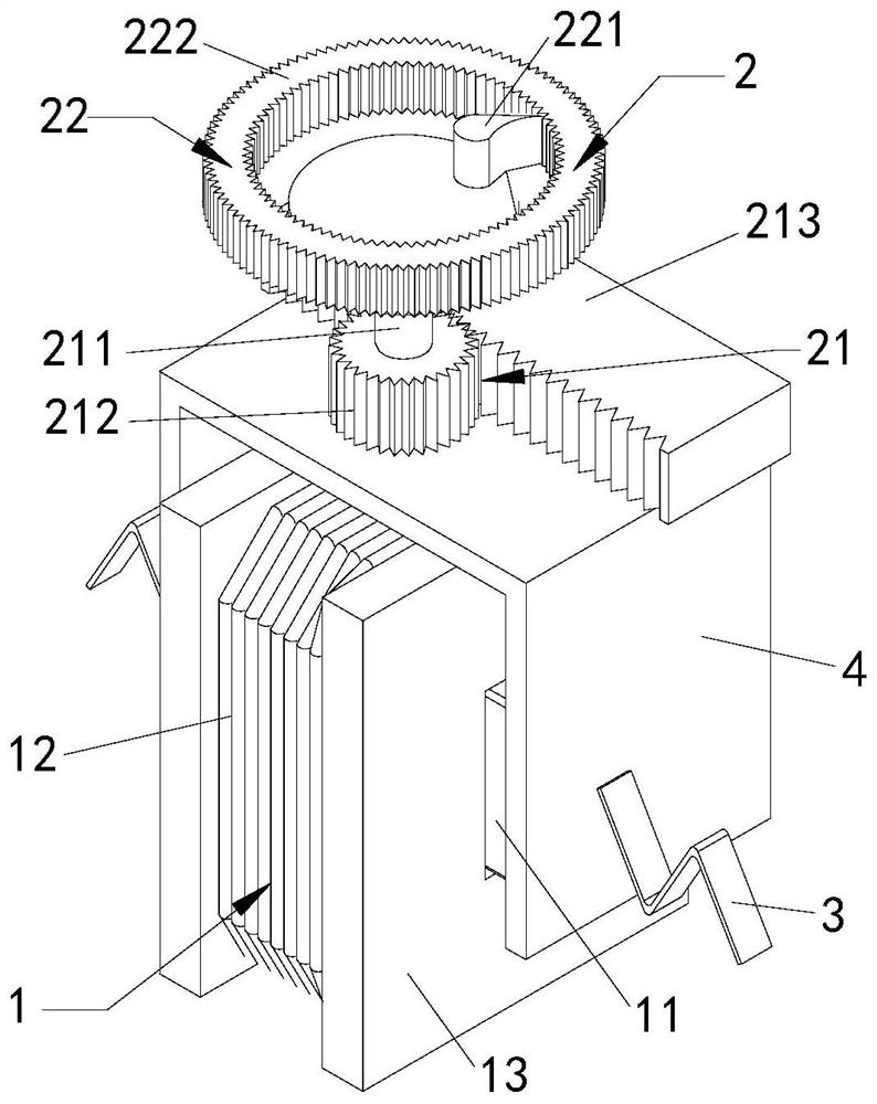
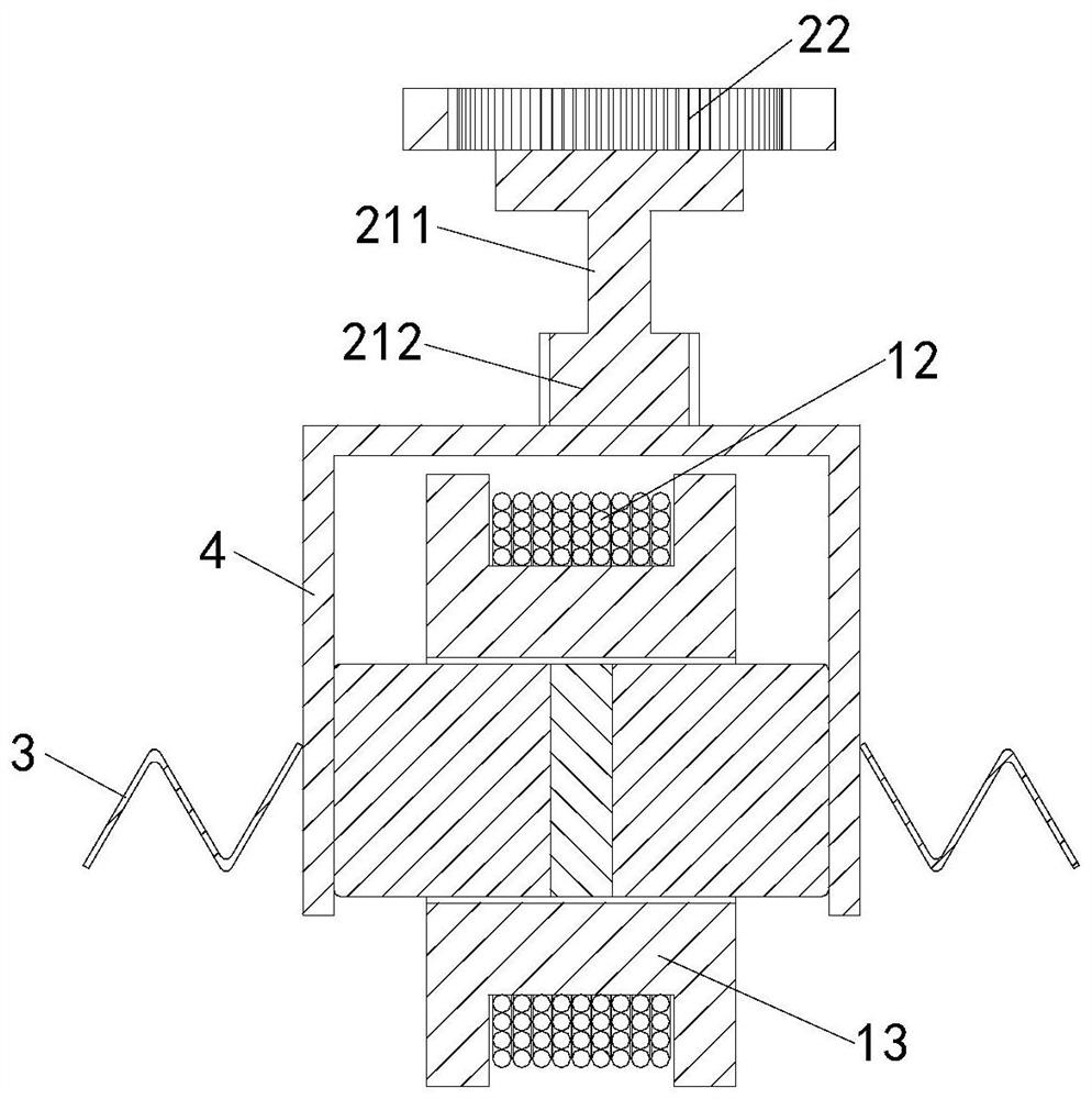
[0025] Such as figure 1 and figure 2 As shown, the present invention provides a reverse magnetic linear drive stepper motor, including a power unit 1 and a transmission unit 2 connected to the power unit 1, and the power unit 1 includes a reverse magnetic magnet 11 and is arranged on the reverse magnetic The coil group 12 on the periphery of the magnet 11, the transmission unit 2 includes a tooth row group 21 and a ratchet group 22 abutting against the tooth row group 21; the ratchet group 22 includes a ratchet 221 arranged on the upper part of the rotating shaft 211 and The ring gear 222 is disposed on the periphery of the ratchet 221 . The power unit 1 is used to generate power, and the transmission unit 2 is used to transmit the power of the power unit 1. During the power transmission process of the transmission unit 2, when the reverse magnetic linear drive step After the motor receives a pulse signal, the coil group 12 will generate a pulse movement along the circumfer...

Embodiment 2

[0030] Such as figure 1 and figure 2 As shown, as another preferred embodiment of the present invention, the reverse magnetic linear drive stepper motor further includes a rack 4 arranged between the power unit 1 and the transmission unit 2, and the reverse magnetic magnet The two ends of 11 are respectively connected with the inside of the rack 4; the rack 21 is U-shaped, the shaft 211 extends out of the rack 4, and the bottom of the shaft 211 is connected to the coil group 12 connected. The gear rack 4 facilitates the installation of the power unit 1 and the transmission unit 2, and protects the power unit 1, improving its safety performance.

[0031] A reset structure 3 is provided on the outer side of the rack 4, and the reset structure 3 is a reset spring or a reset elastic piece.

Embodiment 3

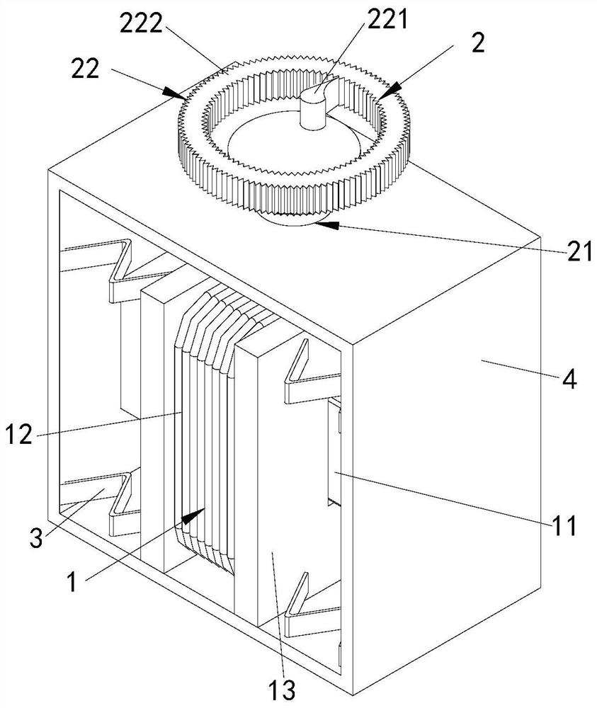
[0033] combine image 3 and Figure 4 As shown, as another preferred embodiment of the present invention, the gear rack 4 is in the shape of a quadrangular frame, the rotating shaft 211 protrudes from the gear rack 4, and the bottom of the rotating shaft 211 is connected to the coil group 12 . The gear rack 4 facilitates the installation of the power unit 1 and the transmission unit 2, and protects the power unit 1, improving its safety performance.

[0034] A reset structure is provided between the gear rack 4 and the coil winding block 13, and the reset structure is a reset spring or the reset elastic piece.

[0035] During the use of the reverse magnetic linear drive stepper motor of the present invention, when the PWM pulse signal directly drives the reverse magnetic magnet 11, the reverse magnetic magnet 11 and the coil group 12 will generate a pulse similar to the pulse signal. Compared with the traditional stepping motor, the response time is shorter, and the tooth r...


PUM


Abstract

The invention provides a reversed magnetic linear drive stepping motor, comprising a power unit and a transmission unit connected with the power unit, wherein the power unit comprises a reversed magnetic magnet and a coil group arranged at the periphery of the reversed magnetic magnet, and the transmission unit comprises a tooth row group and a ratchet group abutting on the tooth row group. The power unit is used for generating power, the transmission unit is used for transmitting the power of the power unit, during the power transmission of the transmission unit, after the reversed magnetic linear drive stepping motor receives a pulse signal, the coil set will generate a pulsed motion in the circumferential direction, the kinetic energy of the impulse motion is transmitted to the ratchetwheel group through the tooth row group, and the ratchet wheel of the ratchet wheel group can drive the tooth ring to rotate by a step angle, so that the structure of the diamagnetic linear driving stepping motor can be simplified, and the step control without out-of-step and with high precision can be achieved.

Description

technical field [0001] The invention relates to the technical field of motors, in particular to an inverse magnetic linear drive stepping motor. Background technique [0002] Stepper motors mainly include three types: reactive type, permanent magnet type and hybrid type. The main structure is to improve the traditional rotor and stator design to comply with the digital control mode that converts electrical pulse signals into mechanical angular displacement. [0003] In the prior art, there are many problems in the stepper motor that will affect the output accuracy of its angular displacement. The main problem comes from the traditional rotor structure, including (1) when the pulse signal is input, the rotor will have a certain inertia residual effect after moving Its stop position; (2) no matter what kind of prior art, all there is distributing phenomenon, because the traditional rotor-stator structure is not suitable for receiving pulse signal. [0004] In addition, steppe...

Claims


Application Information

Patent Timeline
Patent Type & Authority Patents(China)
IPC IPC(8): H02K37/24
CPCH02K37/24
Inventor 程春东
Owner 烟台金钢磁性材料有限公司
Learn More