Electromagnetic interference detection method and system, and electromagnetic interference detector

A technology of electromagnetic interference and detection methods, applied in the fields of electromagnetic field characteristics, instruments, measuring devices, etc., can solve problems such as inability to save historical data, inconvenient portability, and errors in detection results of detection equipment, so as to improve the efficiency of statistical analysis of data and improve the reliability degree, easy to carry

Inactive Publication Date: 2018-11-23
HEXING ELECTRICAL +2
View PDF4 Cites 0 Cited by
  • Summary
  • Abstract
  • Description
  • Claims
  • Application Information

AI Technical Summary

Problems solved by technology

[0002] At present, when the meter is certified and the organization tests the accuracy of the meter, because the meter itself is in the source of interference, the testing equipment has to be in the same source of interference as the meter, but the testing equipment itself often does not have the function of anti-magnetic field interference. , so the strong magnetic field environment will affect the detection sensitivity of the detection equipment, which will lead to errors in the detection results of the detection equipment; moreover, most of the interference sources are strong magnetic fields, which will also bring physical damage to the detection personnel
[0003] In addition, testers or analysts must stand in the test environment to visually identify the light pulses generated by the electric meter in the experiment and analyze the problem. For special requirements with relatively large pulse constants, testers cannot visually identify the accuracy of the pulses. Perform pulse counting, compare the number of pulses in the interference experiment and the total number of pulses in the non-interference experiment, and judge the measurement accuracy of the meter in the interference environment. The existing optical pulse counter can only count the number of pulses; it cannot generate real-time data for the meter. The optical pulse is analyzed, and the historical data cannot be saved, and the experimental data cannot be traced
[0004] To sum up, the existing test equipment is generally expensive, inconvenient to carry, and cannot analyze and save the light pulse, and the experimental data cannot be traced back. At present, there is no simple structure, portability, safe and reliable performance, and data statistics in the industry. Anti-electromagnetic interference electric meter optical pulse detection equipment

Method used


Image

  • Electromagnetic interference detection method and system, and electromagnetic interference detector
  • Electromagnetic interference detection method and system, and electromagnetic interference detector
  • Electromagnetic interference detection method and system, and electromagnetic interference detector

Examples


Embodiment 1

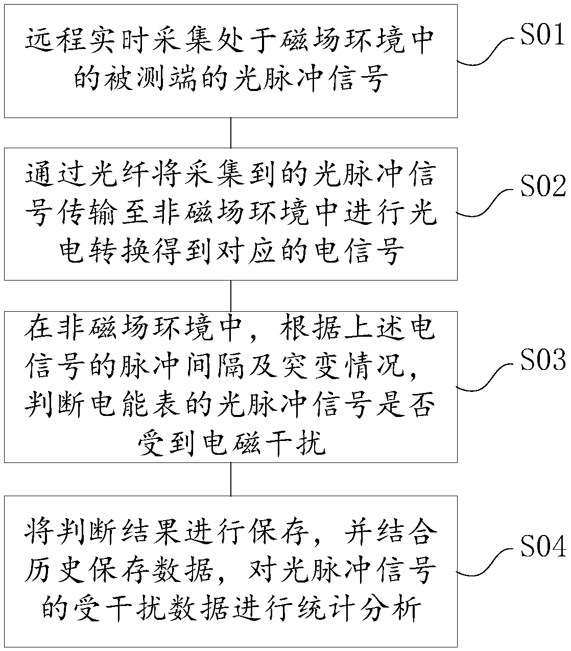
[0039] An electromagnetic interference detection method, such as figure 1 shown, including the following steps:

[0040] S01: remote real-time collection of optical pulse signals of the tested end in a magnetic field environment;

[0041] By connecting the optical fiber inlet to the electric energy meter to be detected, the optical pulse signal of the electric energy meter is collected in real time, and then the optical pulse signal is transmitted to the next link through the optical fiber.

[0042] S02: Transmit the collected optical pulse signal to a non-magnetic field environment through an optical fiber for photoelectric conversion to obtain a corresponding electrical signal;

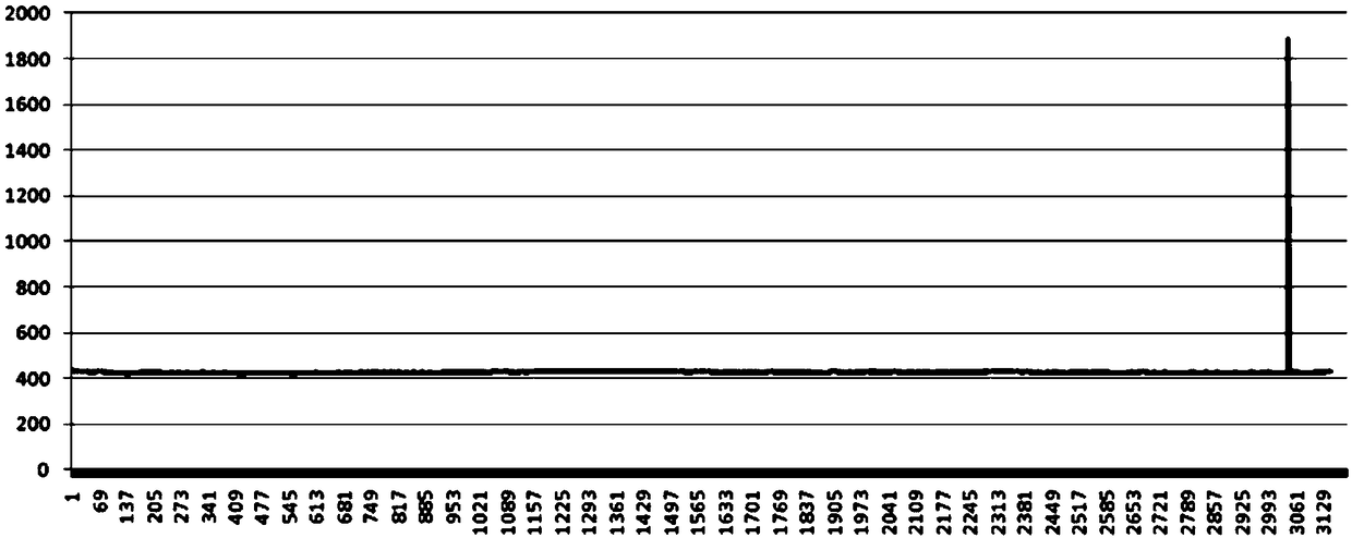
[0043] S03: In a non-magnetic field environment, judge whether the optical pulse signal of the electric energy meter is subject to electromagnetic interference according to the pulse interval and sudden change of the above electrical signal.

[0044] Specifically, the time interval and pulse peak ...

Embodiment 2

[0053] This embodiment provides an electromagnetic interference detection system, refer to figure 2 , the system includes a signal acquisition unit, a photoelectric conversion unit, a signal processing unit, a human-computer interaction unit and a communication unit, wherein the signal acquisition unit and the photoelectric conversion unit are connected through optical fibers, and the photoelectric conversion unit, signal processing unit and human-computer interaction unit are connected through The communication units are connected sequentially; the general measurement situation is: the photoelectric conversion unit, signal processing unit and human-computer interaction unit are all in a non-magnetic field environment, and the measured terminal is in a magnetic field environment;

[0054] specific:

[0055] The signal acquisition unit is connected with the terminal under test (such as: electric energy meter, etc.), and is used to remotely collect the optical pulse signal of t...

Embodiment 3

[0061] This embodiment provides an electromagnetic interference detector, such as image 3 As shown, the electromagnetic interference detector is a box type, including an optical fiber inlet, a photoelectric conversion module, a controller, and an operation panel; wherein, the photoelectric conversion module and the controller are located inside the box-type detector, and the optical fiber inlet is located in the box The top of the box-type detector, and the operation panel is located at the front end of the box-type detector. The specific connection relationship is: the optical fiber inlet, the photoelectric conversion module, the controller and the operation panel are connected in sequence. When performing electromagnetic interference detection, the electromagnetic The optical fiber inlet of the interference detector is connected to the optical fiber inlet of the measured end (electric energy meter, etc.) through an optical fiber.

[0062] specific:

[0063] The optical fib...


PUM


Abstract

The present invention discloses an electromagnetic interference method and system, and an electromagnetic interference detector. The method comprises the following steps of: remotely collecting optical pulse signals of a tested terminal located in a strong electromagnetic field environment in real time; transmitting the collected optical pulse signals to a non-magnetic field environment by opticalfibers to perform photovoltaic conversion to obtain corresponding electrical signals; determining whether the optical pulse signals are influenced by electromagnetic interference or not according tothe pulse interval of the electrical signals and the mutations in the non-magnetic field environment to determine whether the tested terminal is influenced by the electromagnetic interference or not.Through adoption of the optical fiber communication, the detection device cannot be interfered by the electromagnetic field so as to improve the reliability of a detection result; the electromagneticinterference method and system, and the electromagnetic interference detector can automatically perform statistic analysis for the optical pulse signals so as to avoid the trouble of artificial statistics and improve the data statistics and analysis efficiency; and moreover, the volume is relatively small, the weight in light, the carrying is convenient, and the electromagnetic interference methodand system, and the electromagnetic interference detector are suitable for the optical pulses of visible light with different wavelengths and can be applied to detection occasions.

Description

technical field [0001] The invention relates to electromagnetic anti-interference detection technology, in particular to an electromagnetic interference detection method, system and electromagnetic interference detector. Background technique [0002] At present, when the meter is certified and the organization tests the accuracy of the meter, because the meter itself is in the source of interference, the testing equipment has to be in the same source of interference as the meter, but the testing equipment itself often does not have the function of anti-magnetic field interference. , so the strong magnetic field environment will affect the detection sensitivity of the detection equipment, which will lead to errors in the detection results of the detection equipment; moreover, most of the interference sources are strong magnetic fields, which will also cause physical damage to the detection personnel. [0003] In addition, testers or analysts must stand in the test environment...

Claims


Application Information

Patent Timeline
Patent Type & Authority Applications(China)
IPC IPC(8): G01R35/04G01R29/08
CPCG01R29/0814G01R29/0871G01R35/04
Inventor 高建余海林
Owner HEXING ELECTRICAL
Why Eureka
Try Eureka