
Small shunting type multi-phase flow meter and calibration method thereof

A multiphase flowmeter and split-flow technology, which is applied in the field of small split-flow multiphase flowmeter and its adjustment, can solve the problems of high adjustment cost, troublesome multiphase flow measurement, and long assembly time.

Active Publication Date: 2018-11-23
XINJIANG ZHONGYUAN TIANNENG OIL & GAS TECH CO LTD
View PDF5 Cites 8 Cited by
  • Summary
  • Abstract
  • Description
  • Claims
  • Application Information

AI Technical Summary

Problems solved by technology

Due to the complexity and variability of multiphase fluids, users always doubt the authenticity and reliability of its measurement. The phase flowmeter was the first to be suspected of having a problem, and it was impossible to judge whether the multiphase flowmeter was out of tolerance on site. The only way was to use traditional large-scale separate metering equipment for calibration. The separate metering equipment is bulky and requires a lot of installation and connection work. , especially for high-pressure and high-flow oil and gas wells, the connecting pipes require large hoisting equipment, which takes a long time to assemble
In addition, the multiphase flowmeter itself needs to be adjusted regularly, and the adjustment cost is very high. It takes nearly 10,000 yuan to measure and adjust a medium-high pressure oil and gas well in China, and it costs even It costs tens of thousands of dollars, which is a world problem that has plagued multiphase flow measurement for a long time

Method used


Image

  • Small shunting type multi-phase flow meter and calibration method thereof
  • Small shunting type multi-phase flow meter and calibration method thereof
  • Small shunting type multi-phase flow meter and calibration method thereof

Examples


Embodiment Construction

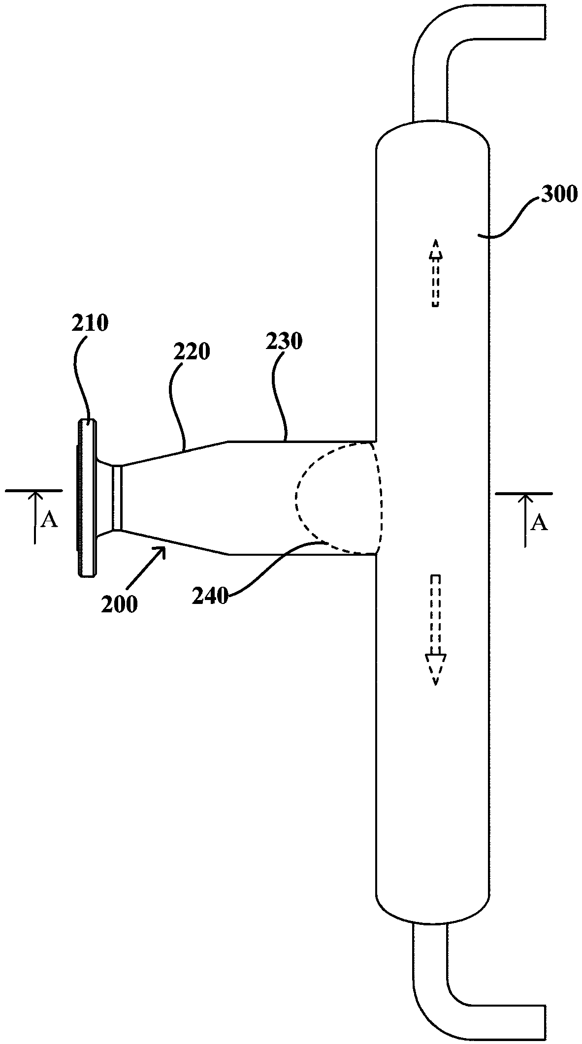
[0073] figure 1 is a schematic diagram of a small split multiphase flowmeter 10 according to one embodiment of the present invention. The small shunt multiphase flowmeter 10 can be applied to the air flow rate of 1×10 by replacing the flow sensor 4 SM 3 / d to 500×10 4 SM 3 In the range of / d, the liquid volume is 1m 3 / d to 1500m 3 In the range of / d, the pressure is in the range of 0.2-42MPa, and its specific pipeline structure may include: fluid inlet pipe 200, shunt pipe 300, first branch 500, second branch 400, and manifold 600 .

[0074] Among the above components, the fluid access pipe 200 is used for accessing gas-liquid fluid. The fluid access pipe 200 may include: a connecting flange 210 , a diameter-expanding pipe section 220 , and a main pipe section 230 . The connecting flange 210 is used for connecting the fluid input pipe, which is suitable for the fluid input pipe. The diameter-expanding pipe section 220 is connected to the connecting flange 210 , and t...


PUM


Abstract

The invention provides a small shunting type multi-phase flow meter and a calibration method thereof. The small shunting type multi-phase flow meter comprises a vertical shunting pipe, a first branchand a second branch, wherein the shunting pipe is used for dividing a gas-liquid two-phase fluid into a first fluid flowing upwards and a second fluid flowing downwards; the first branch is connectedwith an upper outlet of the shunting pipe and used for allowing the first fluid to pass; the second branch is connected with a lower outlet of the shunting pipe and used for allowing the second fluidto pass; the first branch is connected with a first flow regulating valve and a first flow meter body in series, and the second branch is connected with a second flow adjusting valve and a second flowmeter body in series; a flow computer obtains a gas flow comparison reference value measured by the first flow meter body and a liquid flow comparison reference value measured by the second flow meter body under the condition that the first fluid and the second fluid form the single-phase fluid, the gas flow comparison reference value and the liquid flow comparison reference value are compared with gas and liquid flow measured values in a multi-phase flow measuring state, and then the error of the gas flow and the liquid flow is determined. Self-calibration is achieved.

Description

technical field [0001] The invention designs fluid flow measurement, and in particular relates to a small shunt type multiphase flowmeter and its adjustment method. Background technique [0002] Multiphase fluid is a common flow condition in petroleum, chemical industry, pipeline transportation and other fields. At present, in the fields of oil and gas, shale gas, and chemical industry, online non-separated multiphase flow measurement devices are developing rapidly, and various measurement principles and structures emerge in endlessly. [0003] For gas-liquid mixed fluid with high or low gas-liquid ratio, large mixed flow rate, and small liquid phase, it is very difficult for a multiphase flowmeter to accurately measure the gas-liquid two-phase flow; and for gas-liquid mixed fluid with a small gas phase, the flow rate The mixing effect is poor, the fluctuation is large, and the multiphase flow measurement error is large; the existing multiphase flowmeter generally has a sma...

Claims


Application Information

Patent Timeline
Patent Type & Authority Applications(China)
IPC IPC(8): G01F1/00G01F15/08G01F25/00G01D21/02
CPCG01D21/02G01F1/00G01F15/08G01F25/10
Inventor 卢玖庆王良贵董庆丰施斌欧阳雪峰何峰丁勇彬刘刚何宇罗世银张虎王红春
Owner XINJIANG ZHONGYUAN TIANNENG OIL & GAS TECH CO LTD
Learn More