
Automatic purge system and automatic purge method

An automatic, purging technology, used in flushing, lighting and heating equipment, cleaning heat transfer devices, etc., can solve the problem of poor effect of the purging device, save energy consumption, ensure the purging effect, and reduce consumption Effect

Active Publication Date: 2020-06-30
合力正华(北京)工程技术有限公司
View PDF7 Cites 0 Cited by
  • Summary
  • Abstract
  • Description
  • Claims
  • Application Information

AI Technical Summary

Problems solved by technology

[0004] The purpose of the present disclosure is to overcome the deficiencies of the prior art and provide an automatic purging system and automatic purging method to improve the poor effect of existing purging devices

Method used


Image

  • Automatic purge system and automatic purge method
  • Automatic purge system and automatic purge method
  • Automatic purge system and automatic purge method

Examples


Embodiment Construction

[0020] The objectives and technical solutions in the embodiments of the present disclosure will be further described in detail below in conjunction with the accompanying drawings in the embodiments of the present disclosure. Please note that in order to clearly show the structure of each part of the embodiments of the present disclosure, the drawings are not necessarily drawn in the same scale, and the same or similar reference signs are used to represent the same or similar parts. The embodiments shown and described here are only some embodiments of the present disclosure, but not all embodiments. With regard to the embodiments in the present disclosure, all other embodiments provided by those skilled in the art without creative efforts shall fall within the protection scope of the present disclosure.

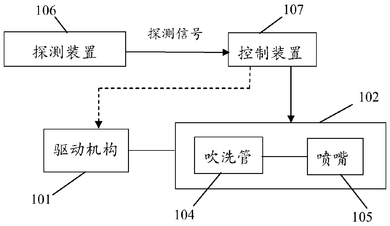
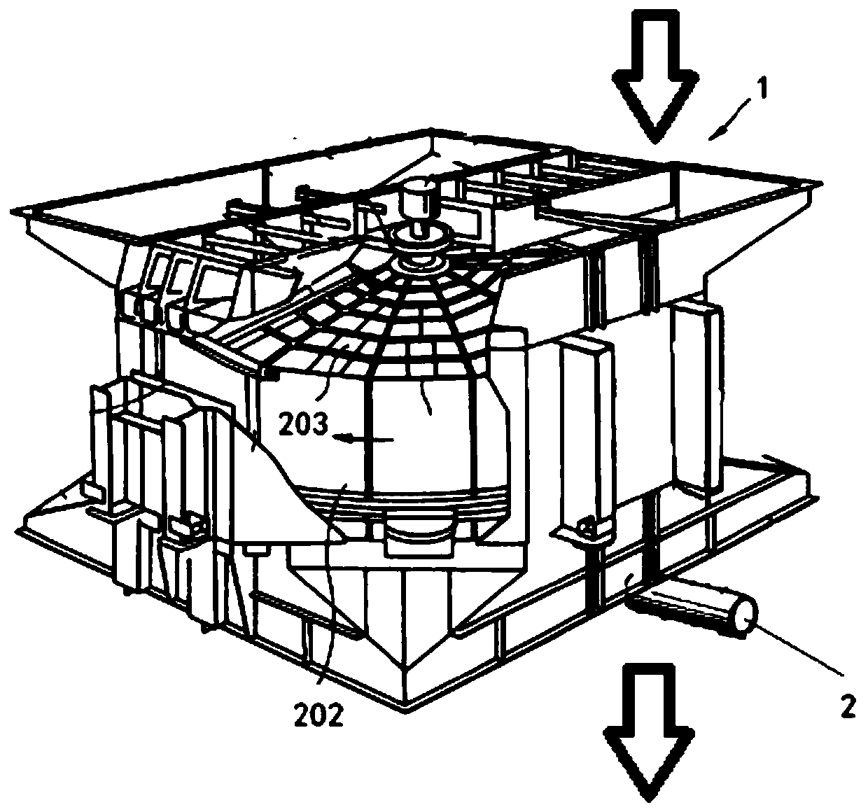
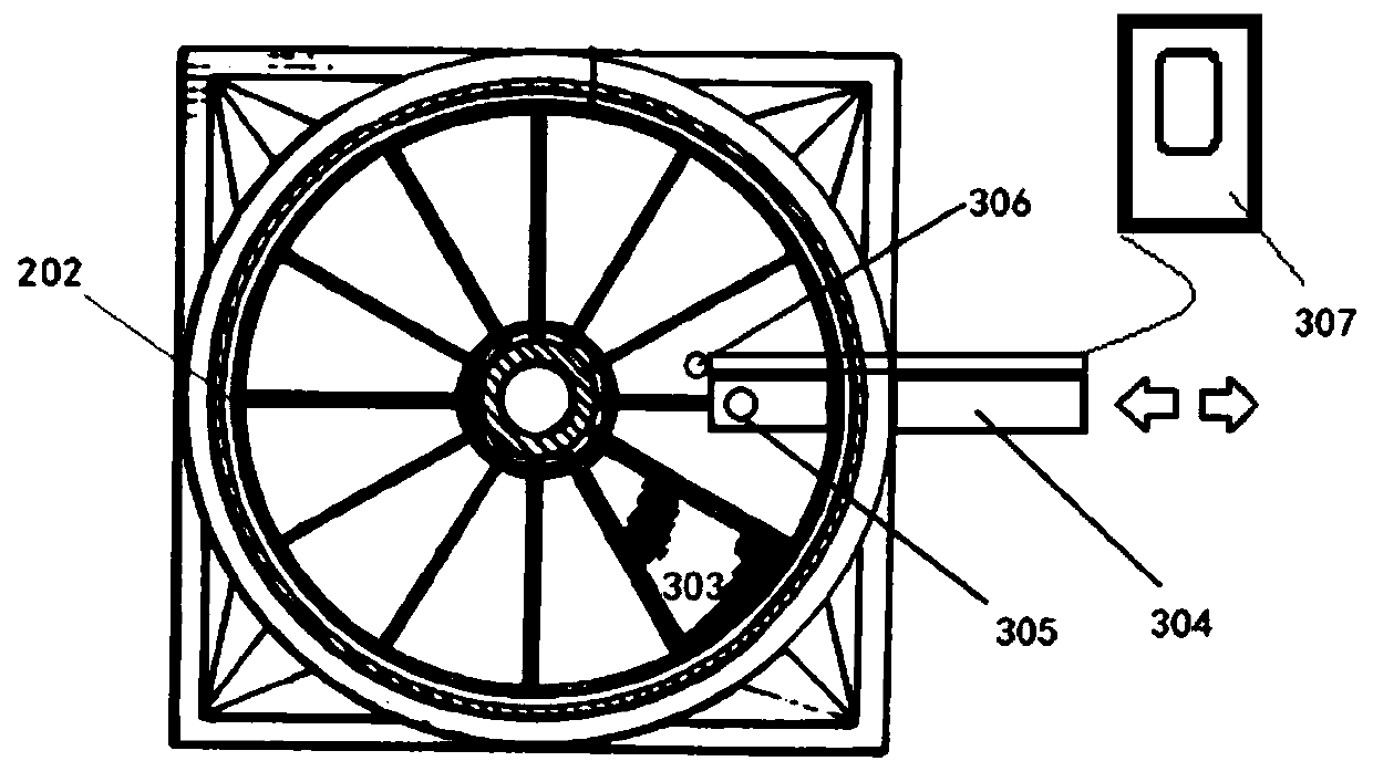
[0021] figure 1 It is a structural schematic diagram of the automatic purging system of the embodiment of the present disclosure. Such as figure 1 As shown, the automatic f...


PUM


Abstract

The present disclosure provides an automatic purging system and method. The automatic purging system includes a purging device, a detection device attached to the purging device, a driving mechanism that drives the purging device to move in a direction parallel to the surface to be cleaned, and a control device. The detection device is used to detect the flow of air respectively. The flow rate of each area on the surface to be cleaned is determined and a detection signal is sent to the control device. The control device determines the flow rate (V 1 ) relative to the flow velocity (V 0 ) ratio (V 1 / V 0 ) to determine whether there is dust accumulation in each area, and control the purging device to purge the areas determined to be dust accumulation. The automatic purging system and method of the present disclosure can automatically detect whether and the degree of dust accumulation on the heat exchange surfaces of different parts of the heat exchanger, and automatically control the purging process based on the detection results. Moreover, this system can reduce the risk of equipment being blown out and reduce the consumption of purging media.

Description

technical field [0001] The disclosure belongs to the field of industrial cleaning, and relates to a purging system and method for heat exchange surfaces of various heat exchangers such as power plant boilers, industrial boilers, and economizers, as well as flue gas denitrification catalysts, in particular to an automatic Purge system and automatic purge method. Background technique [0002] The heat exchanger is a heat exchange device commonly used in power plant boilers and flue gas desulfurization systems. It uses the heat of the flue gas discharged from the boiler to heat the air required for combustion and the net flue gas after desulfurization, so as to save fuel. and to reduce pollution. Heat exchangers are one of the key auxiliary equipment for boilers and desulfurization systems, including rotary, water-medium, and steam heat exchangers. One of the most important performance indicators of the heat exchanger is the resistance flowing through the heat exchange surfac...

Claims


Application Information

Patent Timeline
Patent Type & Authority Patents(China)
IPC IPC(8): F28G1/16F28G9/00F28G15/00F28G15/04
CPCF28G1/166F28G9/00F28G15/003F28G15/04
Inventor 王绍辰
Owner 合力正华(北京)工程技术有限公司
Learn More