
NoveL ship stabiLizing fin

A fin stabilizer and ship technology, which is applied to equipment for reducing ship movement, using hydrofoils to reduce ship movement on the surrounding water surface, etc., can solve the problem of affecting the normal operation of equipment and instruments, large internal space of the hull, and reducing the seaworthiness of the ship and other issues to achieve the effect of improving airworthiness, improving anti-rolling effect, and reducing drag

Active Publication Date: 2018-11-23
ZHEJIANG OCEAN UNIV
View PDF7 Cites 11 Cited by
  • Summary
  • Abstract
  • Description
  • Claims
  • Application Information

AI Technical Summary

Problems solved by technology

[0002] When a ship encounters wind and waves during navigation, it will sway laterally. The lateral sway of the ship will reduce the seaworthiness of the ship, damage the hull structure, affect the normal operation of equipment and instruments, and cause cargo displacement or impact damage , will also make passengers faint. In order to reduce the lateral roll of the ship, the best solution at present is to install stabilizer fins on the bottom of the ship's side
Most of the existing fin stabilizers are integral structures. If the fin stabilizer is large in size, it will occupy a large space inside the hull when stowed, and the requirements for the retractable device are also high. If the fin stabilizer is small in size, it cannot be easily Good for shaking

Method used


Image

  • NoveL ship stabiLizing fin
  • NoveL ship stabiLizing fin
  • NoveL ship stabiLizing fin

Examples


Embodiment Construction

[0031] Below are specific embodiments of the present invention and in conjunction with accompanying drawing, technical scheme of the present invention is described further, but the present invention is not limited to these embodiments.

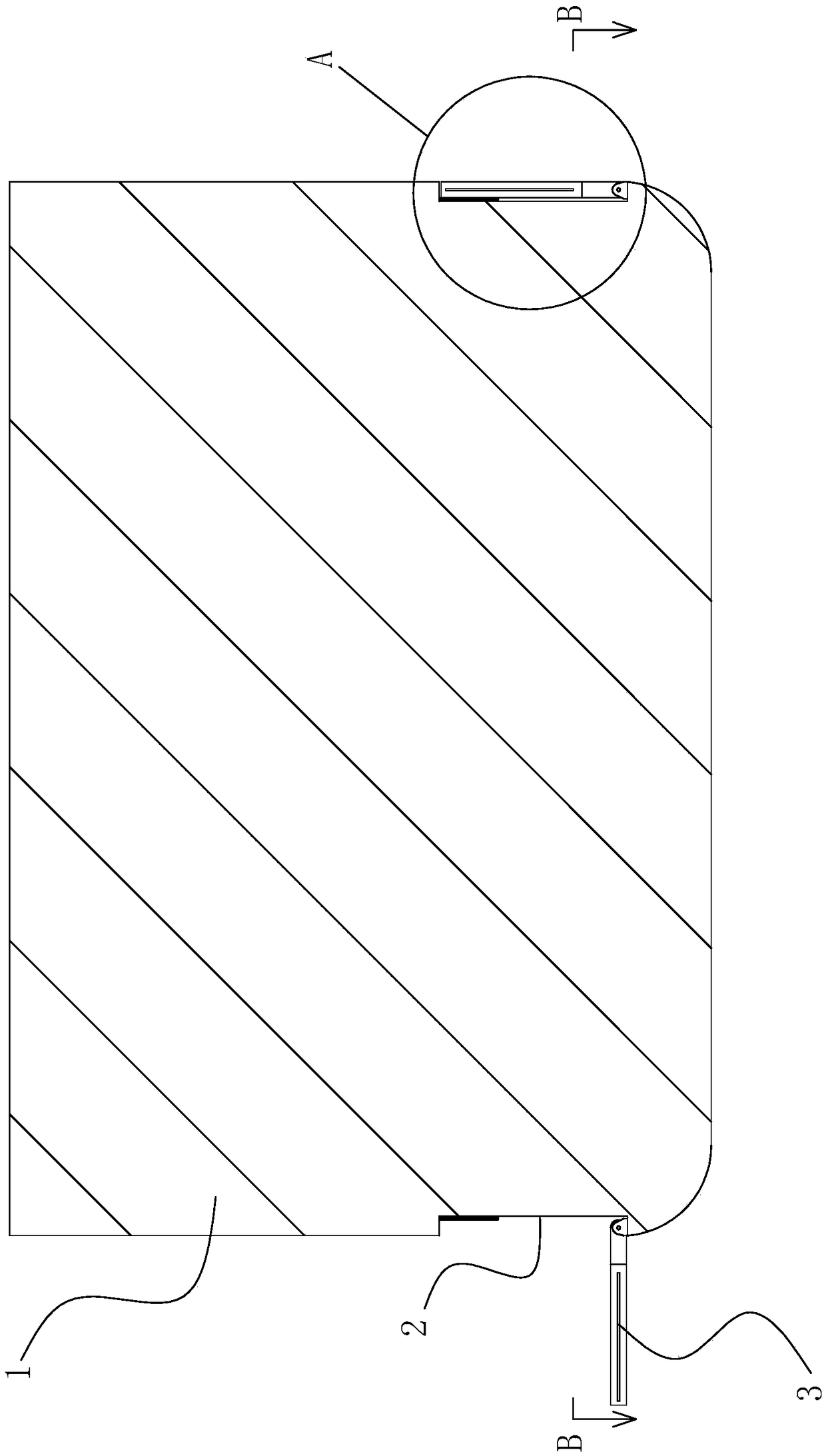
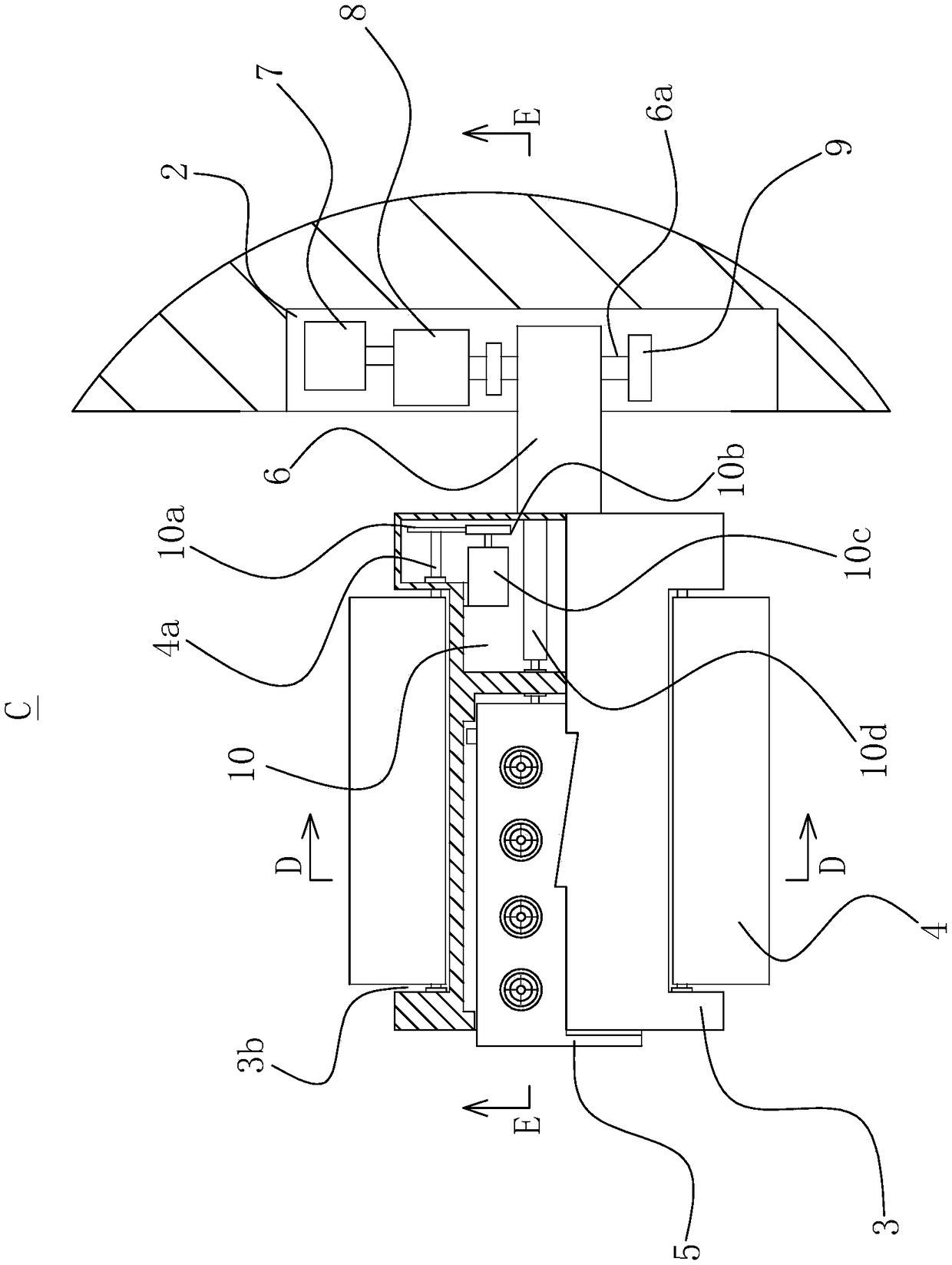
[0032] refer to Figure 1 to Figure 7 , a new ship stabilizer fin, the new ship stabilizer fin installed on both sides of the hull structure 1, the bottom of the two sides of the hull structure 1 are provided with installation grooves 2, the installation groove 2 is set There are anti-collision pads 14, and the new ship fin stabilizer includes a fin stabilizer body 3, and also includes a rotating body 6, a motor one 7, a reducer 8 and two bases 9, and the motor one 7 and the base 9 are all provided with On the lower end surface of the installation groove 2, the rotating body 6 is fixed with a rotating shaft 6a, and the two ends of the rotating shaft 6a are respectively rotated and arranged on the base 9, and the output end of the motor one 7 pas...


PUM


Abstract

The invention provides a noveL ship stabiLizing fin, and beLongs to the technicaL fieLd of marine equipment. The noveL ship stabiLizing fin comprises a stabiLizing fin body, a rotating body, a first motor and a speed reducer, the stabiLizing fin body is fixedLy connected with the rotating body, the stabiLizing fin body incLudes a teLescopic wing pLate and a hydrauLic oiL cyLinder, the stabiLizingfin body is provided with a storage cavity and a first mounting cavity, the storage cavity is disposed outside the stabiLizing fin body, the teLescopic wing pLate is sLidabLy disposed in the storage cavity, the first mounting cavity is disposed on the side, cLose to the rotating body, of the stabiLizing fin body, the hydrauLic oiL cyLinder is disposed in the mounting cavity, the end of a piston rod of the hydrauLic oiL cyLinder penetrates through the first mounting cavity and extends into the storage cavity, and the end of the piston rod of the hydrauLic oiL cyLinder is hinged to the teLescopic wing pLate. The fin uses the hydrauLic oiL cyLinder to push the teLescopic wing pLate in different sea conditions to adjust the force receiving area of the stabiLizing fin, and improves the safety and seaworthiness of a ship.

Description

technical field [0001] The invention belongs to the technical field of ship equipment, and relates to a novel ship stabilizer fin. Background technique [0002] When a ship encounters wind and waves during navigation, it will sway laterally. The lateral sway of the ship will reduce the seaworthiness of the ship, damage the hull structure, affect the normal operation of equipment and instruments, and cause cargo displacement or impact damage , It will also make passengers faint. In order to reduce the lateral roll of the ship, the best solution at present is to install fin stabilizers on the bottom of the ship's side. Most of the existing fin stabilizers are integral structures. If the fin stabilizer is large in size, it will occupy a large space inside the hull when stowed, and the requirements for the retractable device are also high. If the fin stabilizer is small in size, it cannot be easily Good to play a role in stabilizing. Contents of the invention [0003] The pu...

Claims


Application Information

Patent Timeline
IPC IPC(8): B63B39/06
CPCB63B39/06B63B2039/065
Inventor 陈正寿孙孟
Owner ZHEJIANG OCEAN UNIV
Learn More