Protective dismounting machine for tires

A protective tire technology, applied in tire installation, tire parts, transportation and packaging, etc., can solve the problems of crowbar damage to the paint surface of the rim surface, effort, damage to the rim, etc.

Inactive Publication Date: 2018-11-23
HEFEI CAREER TECHNICAL COLLEGE
View PDF0 Cites 1 Cited by
  • Summary
  • Abstract
  • Description
  • Claims
  • Application Information

AI Technical Summary

Problems solved by technology

In fact, in addition to the aesthetic factors, the modification of the wheel hub can also achieve the purpose of improving heat dissipation and light weight. The modification of the wheel hub generally chooses a larger size hub, and the larger size hub needs to be matched with a tire with a low aspect ratio to ensure that the size of the hub In the case of larger size, the speed per hour is the same as that of the original car, and when the tire with low aspect ratio is assembled with the rim, it is often necessary to remove the tire pressure sensor on the original wheel rim and install it on the new wheel hub, and then install the tire During the process, the inner side of the tire will collide with the tire pressure sensor. At this time, the worker will use a crowbar to insert between the tire and the hub, and then use the hub as a fulcrum to pry the inner edge of the tire to make the inner edge of the tire outside Flip until the tire pressure sensor is out of the way. This process generally requires two to three workers to complete, and it is very laborious. At the same time, the crowbar will damage the paint on the surface of the rim, and in severe cases, the rim itself will be damaged.

Method used


Image

  • Protective dismounting machine for tires
  • Protective dismounting machine for tires
  • Protective dismounting machine for tires

Examples


Embodiment Construction

[0024] Below in conjunction with the accompanying drawings and embodiments of the description, the specific embodiments of the present invention are described in further detail:

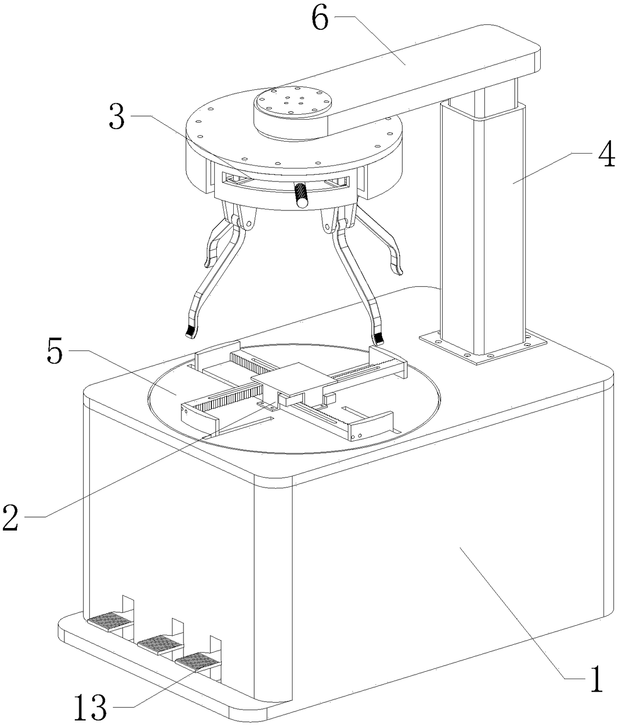
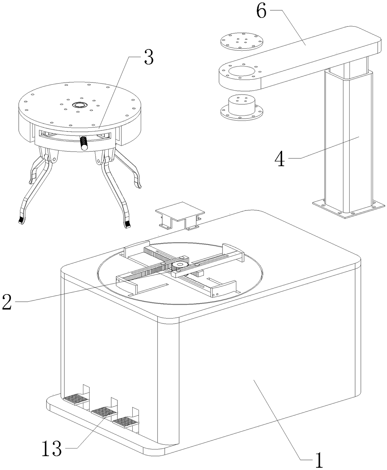
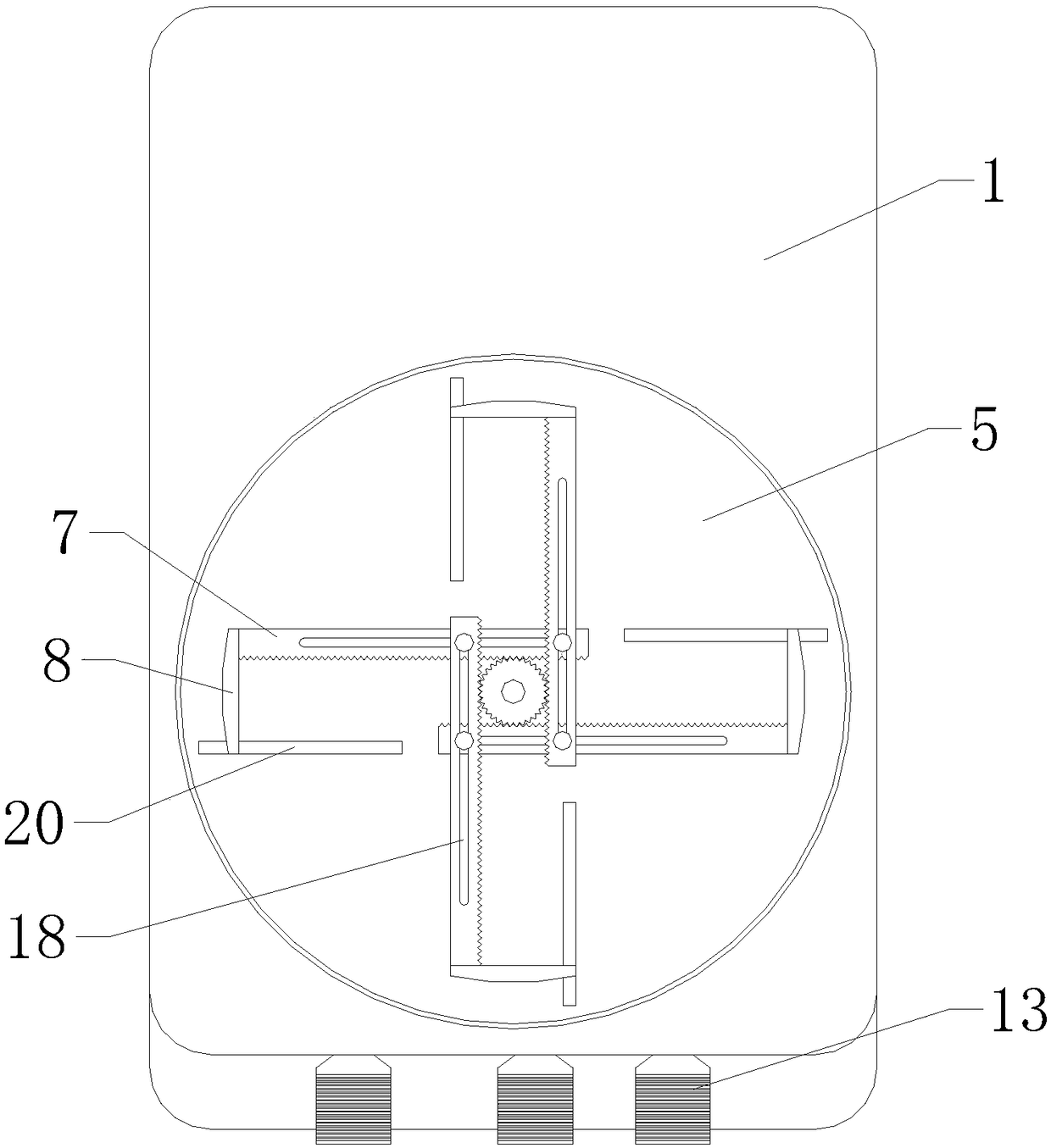
[0025] refer to Figure 1 to Figure 13 The shown protective disassembly and assembly machine for tires includes a workbench 1, a positioning mechanism 2, a selvedge mechanism 3 and a hydraulic lifting arm 4. A hydraulic turntable 5 is horizontally arranged on the top of the workbench 1, and the positioning mechanism 2 is arranged on the On the top of the hydraulic turntable 5, the hydraulic lifting arm 4 is vertically arranged at one end of the top of the workbench 1, the edge-stripping mechanism 3 is horizontally arranged directly above the positioning mechanism 2, and the top of the edge-stripping mechanism 3 is provided by a horizontally arranged support arm 6 is fixedly connected with the top of the hydraulic lifting arm 4. The positioning mechanism 2 includes four horizontally arranged interfere...


PUM


Abstract

The invention relates to the field of tire dismounting tools, in particular to a protective dismounting machine for tires. The protective dismounting machine for the tires comprises a working table, alocating mechanism, a trimming mechanism and a hydraulic lifting arm, wherein a hydraulic swivel plate is horizontally arranged on the top of the working table; the locating mechanism comprises fourcontact rods and a rotating motor; the outer end of each contact rod is connected with an abutting block; the trimming mechanism comprises a circular containing plate and four derrick masts; the circular containing plate is internally provided with a shifting plate used for shifting the derrick masts; the side face of the shifting plate is connected with a push rod extending out of the circular containing plate; a plurality of pedal switches are arranged at the bottom of the lateral part of the working table. The protective dismounting machine for the tires can quickly perform the tire mounting operation of the low flatness ratio tire in a labor-saving way, avoids the situation that the low flatness ratio tire collides with a tire pressure sensor during installation, so that the tire pressure sensor is damaged, and effectively protects the rim from damage.

Description

technical field [0001] The present invention relates to the field of tire changing tools, in particular to a protective changing machine for tires. Background technique [0002] Wheel modification refers to the modification of the original wheel hub of the vehicle for the sake of aesthetics or other purposes by the car owner or professional vehicle modification. , The modification of the wheel hub has gradually become the focus of car fans' modification of the car. The modification of the wheel hub is a more conspicuous modification. From the visual sense, it can be directly judged whether a car has been modified with the wheel hub. Therefore, many people mistakenly think that the wheel hub upgrade is not only for the purpose of Beautiful and eye-catching. In fact, in addition to the aesthetic factors, the modification of the wheel hub can also achieve the purpose of improving heat dissipation and light weight. The modification of the wheel hub generally chooses a larger si...

Claims


Application Information

Patent Timeline
IPC IPC(8): B60C25/05
CPCB60C25/0503B60C25/0521B60C25/0539B60C25/059
Inventor 顾友民解云王鸣
Owner HEFEI CAREER TECHNICAL COLLEGE
Why Eureka
Try Eureka