Method for installing low-voltage cable transformation platform

An installation method and low-voltage cable technology, which are applied in the field of transformer tables, can solve problems such as large manpower consumption, low gravity of utility poles, and potential safety hazards

Pending Publication Date: 2022-02-11
广西中复工程技术有限公司
View PDF0 Cites 0 Cited by
  • Summary
  • Abstract
  • Description
  • Claims
  • Application Information

AI Technical Summary

Problems solved by technology

Among them, when the current supporting elements support the transformer table, the transformer table is directly placed on the carrier plate, and because the utility pole is stable for subsequent support, the utility pole is in a thin upper and thicker structure, so that the utility pole The gravity is low, and it will not fall over. Furthermore, the current support elements cannot support the side upwards and at the same time make the transformer table close to the utility pole at all times. The pressure tables push each other to stick to the poles. Since the transformer tables are mostly made of metal and have a large weight, this process will consume a lot of manpower and cause great safety hazards.

Method used


Image

  • Method for installing low-voltage cable transformation platform
  • Method for installing low-voltage cable transformation platform
  • Method for installing low-voltage cable transformation platform

Examples


Embodiment 1

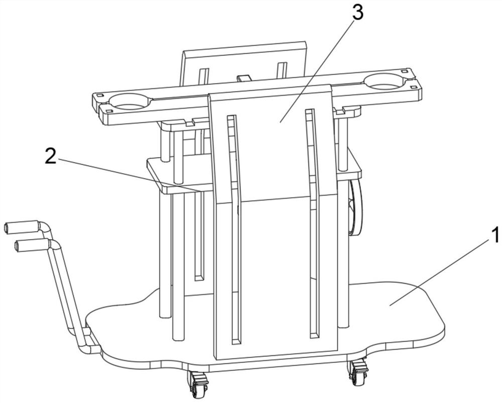
[0045] see Figure 1-Figure 6 As shown, the purpose of this embodiment is to provide a low-voltage cable transformer installation method, which specifically includes the following steps:

[0046] S1. Push the supporting element between the two utility poles;

[0047] S2. Place the two single transformer tables oppositely on the supporting block of the supporting element. The transformer table and the two utility poles are located between the two transformer tables, and are at the same level as the arc opened on the surface of the transformer table. horizontal line;

[0048] S3. The support element is normally driven, and the upward movement of the carrier block makes the transformer table be driven upward synchronously, and the transformer table moves upward along the surface of the utility pole. When the height from the ground is reached, the support element stops working;

[0049] S4. Push the two transformer tables relative to each other, the arc on the surface of the tra...

Embodiment 2

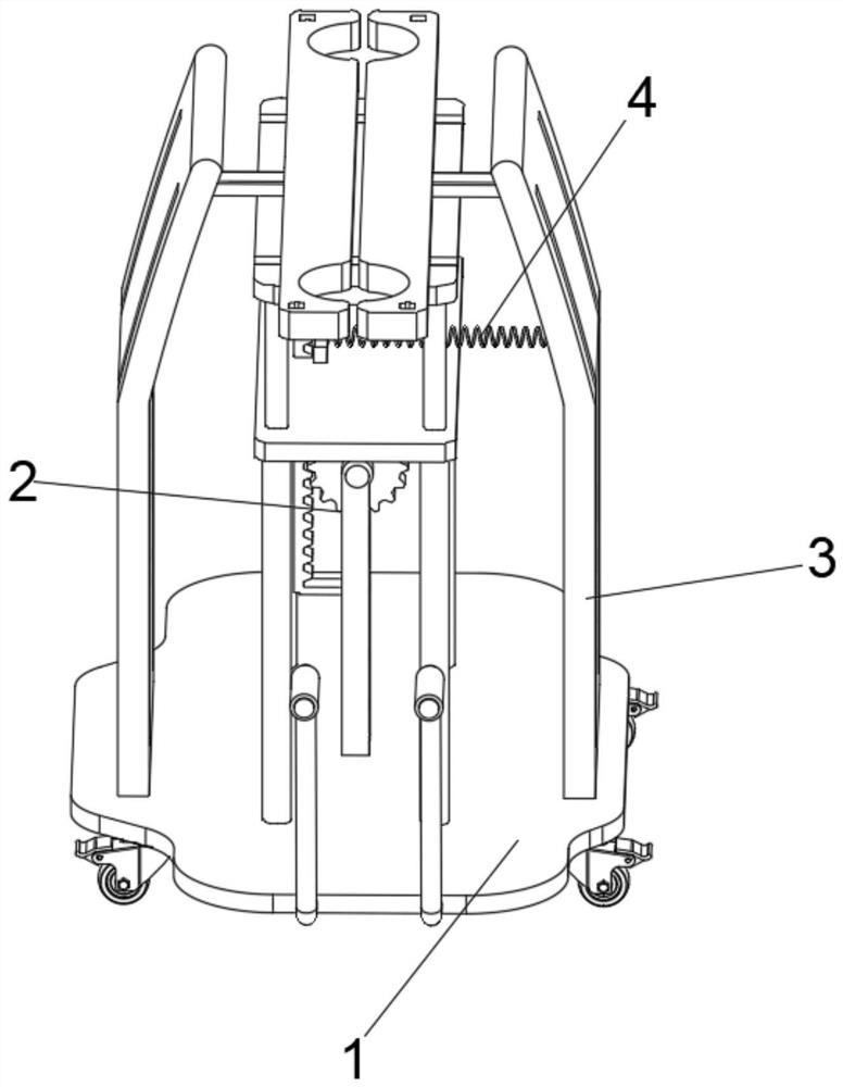
[0057] In order to prevent the platen body 25 from being overturned sideways due to the extrusion force of the side guide block 253, please refer to Figure 7 and Figure 11 Shown:

[0058] The inner side of the jacking assembly 2 is provided with a limit assembly 5, the limit assembly 5 includes a connecting shaft 51, the connecting shaft 51 is installed on the other side of the shaft, and one end of the connecting shaft 51 is equipped with a connecting gear 52, and the surface of the connecting gear 52 is engaged A connecting rack 53 is connected, and a connecting plate 57 is installed on the side of the connecting rack 53. One side of the connecting plate 57 is provided with a circular cavity, and one of the outer fixed shafts 21 is socketed with the circular cavity, and the top of the connecting rack 53 is connected Limiting plate 54, and limiting plate 54 is positioned at the directly below platen body 25, and the surface of limiting plate 54 is provided with the guide r...


PUM


Abstract

The invention relates to the technical field of transformer tables, in particular to a method for installing a low-voltage cable transformer platform. The method specifically comprises the following steps that a supporting element is pushed to the position between two telegraph poles; two single transformation tables are oppositely placed on a carrying block of the supporting element, and the transformation tables and the two telegraph poles are located between the two transformation tables; the supporting element is normally driven, the carrying block moves upwards to enable the transformation tables to be synchronously and upwards driven, the transformation tables are upwards along the surface of the telegraph poles, and when the supporting element reaches the adaptive height from the ground, the supporting element stops working; the two transformation tables are relatively pushed to be close to each other, arc openings in the surfaces of the transformation tables clamp the surface of the telegraph poles, then the two transformation tables are connected through bolt pieces, and bolts enter along the bolt piece holes to lock the two transformation tables. A top plate faces upwards, the guide blocks make contact with the inner walls of the side plates, the guide blocks extrude a platen body to get close after being limited by the inner walls of the side plates, the arc opening of the platen body is attached to the telegraph pole all the time, and manual secondary pushing is not needed.

Description

technical field [0001] The invention relates to the technical field of transformer tables, in particular to a method for installing a low-voltage cable transformer table. Background technique [0002] The transformer table is a component that is used to carry the transformer by two separate plates that are sleeved on the outside of the utility pole. When the current transformer table is installed, by placing the transformer table on the support element, the staff drives the support element so that the transformer table moves upward on the support element. After the transformer table reaches a suitable height from the ground, The supporting elements stop and workers bolt the two transformer tables together. Among them, when the current supporting elements support the transformer table, the transformer table is directly placed on the carrier plate, and because the utility pole is stable for subsequent support, the utility pole is in a thin upper and thicker structure, so that...

Claims


Application Information

Patent Timeline
IPC IPC(8): H01F27/06
CPCH01F27/06
Inventor 赵满根刘敏沈剑钦李艳华欧国平陆建杨振传
Owner 广西中复工程技术有限公司
Why Eureka
Try Eureka