
Particulate matter bed layer support structure and high flux axial reactor

A technology of supporting structure and particulate matter, which is applied in the field of high-flux axial reactors, can solve the problems of complex process design and equipment manufacturing of radial reactor structures, limited popularization and application, and bed thickness, etc., so as to reduce the occurrence of side reactions. chance, increased total surface area, increased processing power

Active Publication Date: 2018-11-23
SINOPEC ENG +1
View PDF10 Cites 0 Cited by
  • Summary
  • Abstract
  • Description
  • Claims
  • Application Information

AI Technical Summary

Problems solved by technology

But this kind of reactor also has some disadvantages: the bed of the catalyst bed is generally thick, and the resistance of the reactants to flow through the bed is large. In order to reduce the resistance, a large particle catalyst must be used; There are high requirements to prevent the catalyst particles from being pulverized by the impact of high-speed airflow
However, the structure of the radial reactor is more complicated than that of the axial reactor in terms of process design and equipment manufacturing, which limits its popularization and application.

Method used


Image

  • Particulate matter bed layer support structure and high flux axial reactor
  • Particulate matter bed layer support structure and high flux axial reactor
  • Particulate matter bed layer support structure and high flux axial reactor

Examples


Embodiment approach

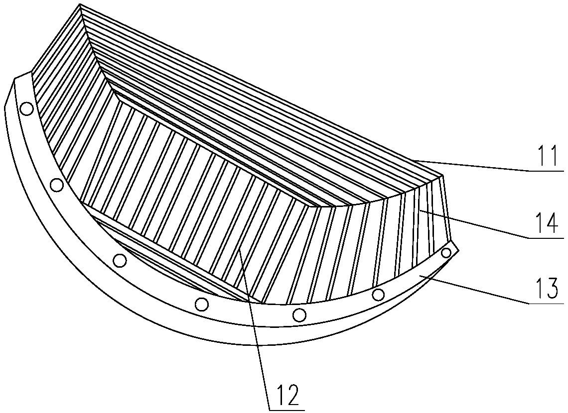
[0039] According to a preferred embodiment of the present invention, the support grid 1 includes a strip-shaped horizontal grid 11, a strip-shaped vertical grid 12, an edge grid 14, and an annular frame 13 that are spliced ​​with each other. The grid 14 is arc-shaped, so that the convex part of the support grid 1 forms a four-sided enclosure structure, and its edge and the bottom surface of the concave part of the support grid 1 are on the same plane, which is convenient for connecting the ring frame 13. This structure can be formed by image 3 It can be clearly seen that the compression grid 2 is formed by splicing a strip-shaped horizontal grid 11 and a strip-shaped vertical grid 12 .

[0040] The protrusions and recesses of the support grid 1 and the compression grid 2 obtained by the above splicing method are respectively composed of parallel strip cuboids, such as Figure 7 shown.

[0041] According to another preferred embodiment of the present invention, the supporting...

Embodiment 1

[0052] This example is used to illustrate the support structure of the particulate matter bed of the present invention.

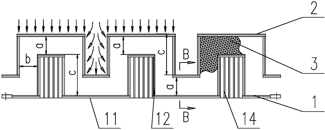
[0053] Such as Figure 2-3 As shown, the support structure of the particulate matter bed layer includes a support grid 1 and a compression grid 2 arranged in the vertical direction, the support grid 1 is located below the compression grid 2, and the support grid 1 and the compression grid 2 have a matching concave-convex structure, so that there is an axial distance a and a lateral distance b between the support grid 1 and the compression grid 2, which is used for setting the particle bed 3.

[0054] The axial spacing a and the lateral spacing b between the support grid 1 and the compression grid 2 are equal, and the axial spacing a and the lateral spacing b between the support grid 1 and the compression grid 2 are also equal, The height c of the vertical grids 12 constituting the supporting grid 1 and the pressing grid 2 are equal.

[0055] The supportin...

Embodiment 2

[0060] This example is used to illustrate the support structure of the particulate matter bed of the present invention.

[0061] The supporting structure of the particle bed layer includes a support grid 1 and a compression grid 2 arranged in the vertical direction, the support grid 1 is located below the compression grid 2, and the support grid 1 and the compression grid The grid 2 has a matching concave-convex structure, so that there is an axial spacing a and a lateral spacing b between the supporting grid 1 and the pressing grid 2, and is used for setting the particle bed 3.

[0062] The axial spacing a and the lateral spacing b between the support grid 1 and the compression grid 2 are equal, and the axial spacing a and the lateral spacing b between the support grid 1 and the compression grid 2 are also equal, The height c of the vertical grids 12 constituting the supporting grid 1 and the pressing grid 2 are equal.

[0063] The support grid 1 and the compression grid 2 e...


PUM


Abstract

The invention relates to the field of petrochemical engineering equipment, and particularly provides a particulate matter bed layer support structure and a high flux axial reactor. The particulate matter bed layer support structure comprises a support grid and a compression grid arranged in the vertical direction, wherein the support grid is positioned under the compression grid; the support gridand the compression grid have the matched concave-convex structure, so that an axial space and a transverse space are formed between the support grid and the compression grid and are used for installing a particulate matter bed layer. Compared with a plane grid support structure with the same diameter, the particulate matter bed layer support structure has the advantages that the circulation areaof the particulate matter bed layer can be increased; the flux of the reaction medium circulation is improved, so that the processing capability of the reactor can be improved; when the processing quantity is identical, the equipment diameter can be reduced; the cost is reduced; the anti-bending cross section modulus of the support structure can be obviously improved. The high-flux reactor provided by the invention can improve the utilization rate of the particulate matter catalyst.

Description

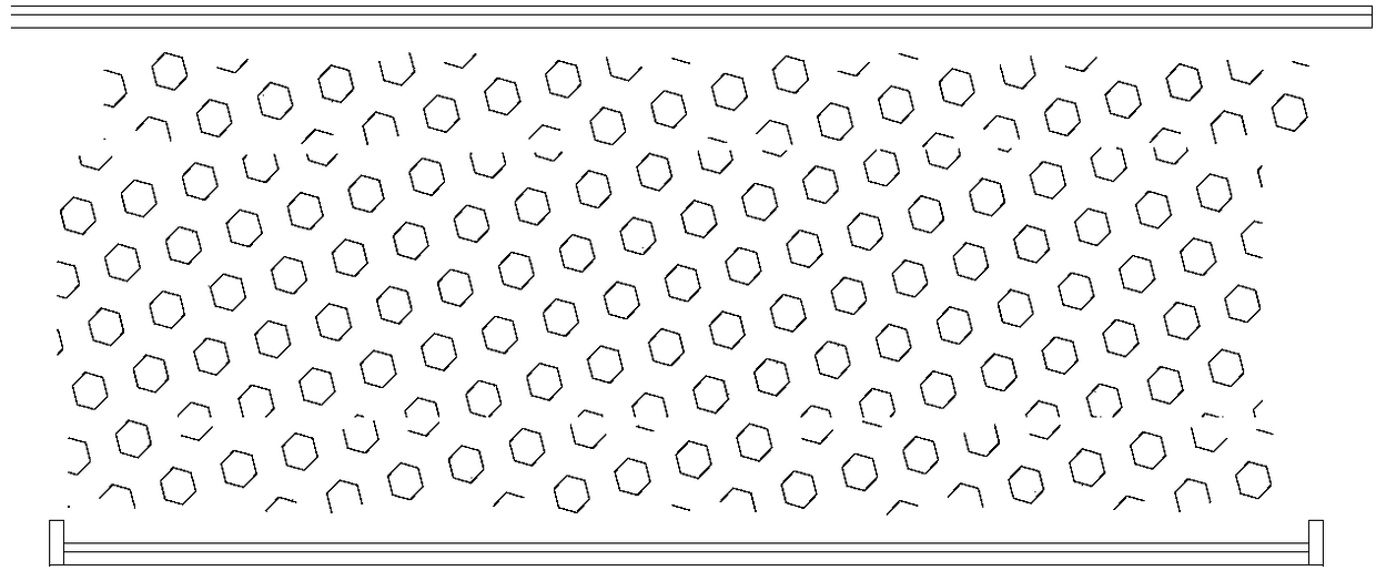
technical field [0001] The invention relates to the field of petrochemical equipment, in particular to a particle bed support structure and a high-throughput axial reactor using the particle bed support structure. Background technique [0002] For the catalyst bed support structure of the reactor, it is generally divided into two types, namely, a planar support grid and a cylindrical support grid. These two support structures correspond to axial flow reactors and radial flow reactors, respectively. Among them, the axial fixed bed reactor has a long history and a wide range of applications. These two reactors include the following characteristics: [0003] Axial fixed bed reactors generally use a planar grid support structure, such as figure 1 shown. The catalyst bed of this type of reactor is arranged in a horizontal cake shape, the fluid flows through the bed from top to bottom along the axial direction, and the bed has no heat exchange with the outside world. The struc...

Claims


Application Information

Patent Timeline
Patent Type & Authority Applications(China)
IPC IPC(8): B01J8/02
CPCB01J8/0242B01J2208/00884
Inventor 郭雪华谢智刚王鑫泉陈志敏朱亚林史倩
Owner SINOPEC ENG
Learn More