Liquid material mixing equipment for chemical industry production
A technology for liquid material and chemical production, which is applied in the field of liquid material mixing equipment for chemical production, and can solve the problems of limited mixing range, insufficient mixing effect, and prolonged mixing time.
- Summary
- Abstract
- Description
- Claims
- Application Information
AI Technical Summary
Problems solved by technology
Method used
Image

Examples
Embodiment 1
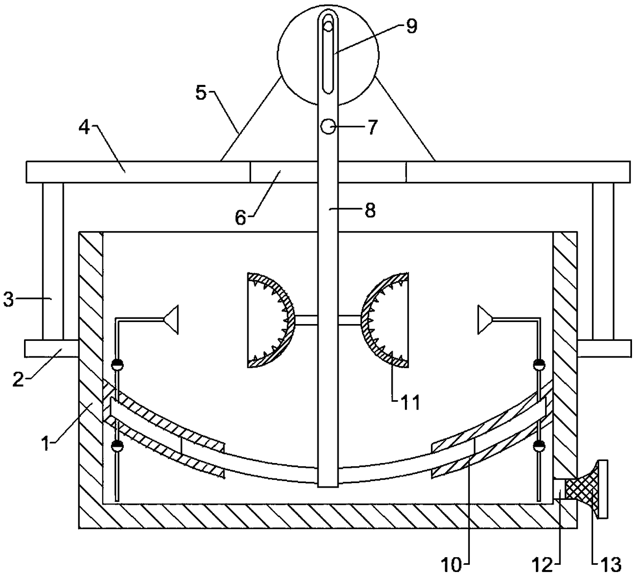
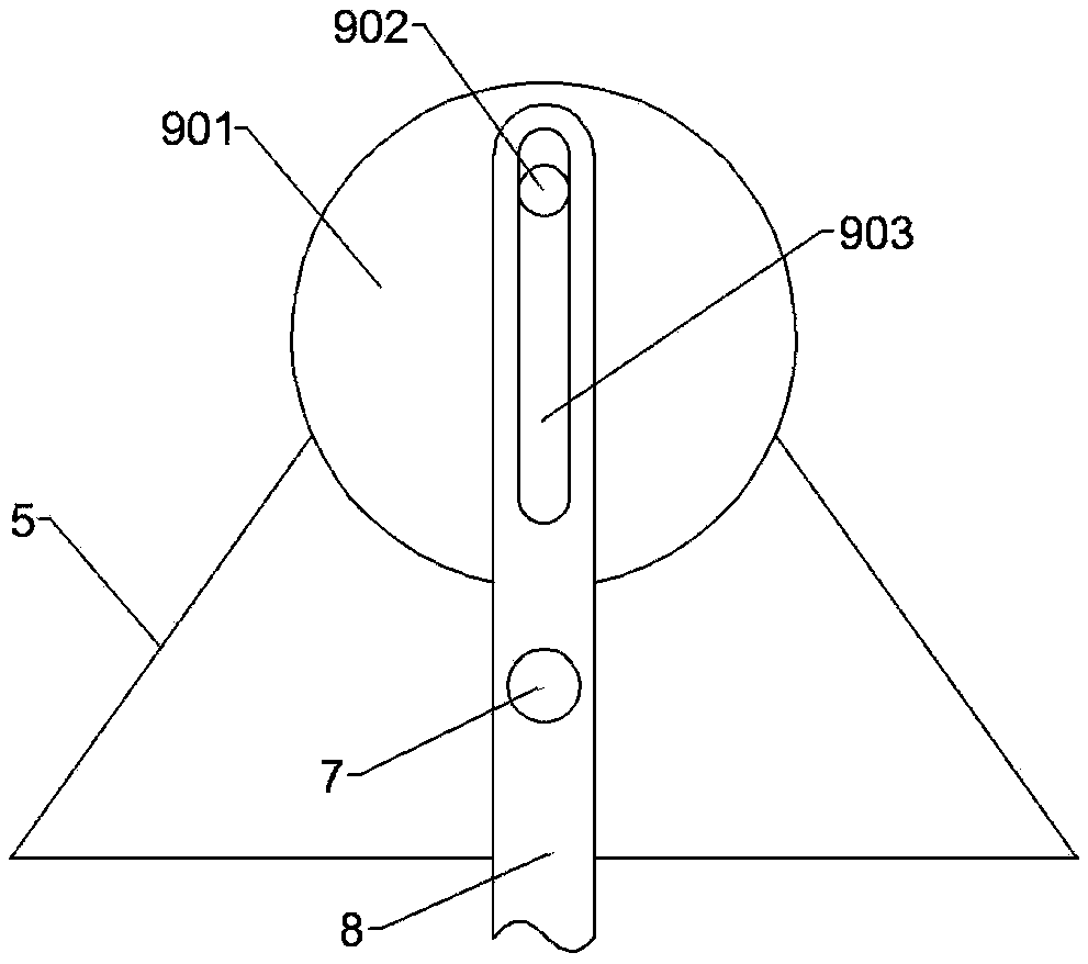
[0026] see figure 1 and figure 2 , in an embodiment of the present invention, a liquid material mixing device for chemical production, including a housing 1, two mounting seats 2 are symmetrically fixedly connected to the outer wall of the housing 1, and vertical columns are fixedly connected to the mounting seats 2 3. The tops of the two vertical columns 3 are fixedly connected with a support plate 4, the support plate 4 is provided with a support frame 5, and the support frame 5 is rotatably connected with a support shaft 7, and the support frame 5 supports the support shaft 7. A swing rod 8 is fixedly connected to the shaft 7, and the upper end of the swing rod 8 is connected with a swing drive device 9, and the swing drive device 9 includes a rotating shaft, which is rotationally connected with the support frame 5, and the rotating shaft is arranged horizontally, and the rear end of the rotating shaft It is fixedly connected with the output shaft of the motor, the front ...
Embodiment 2
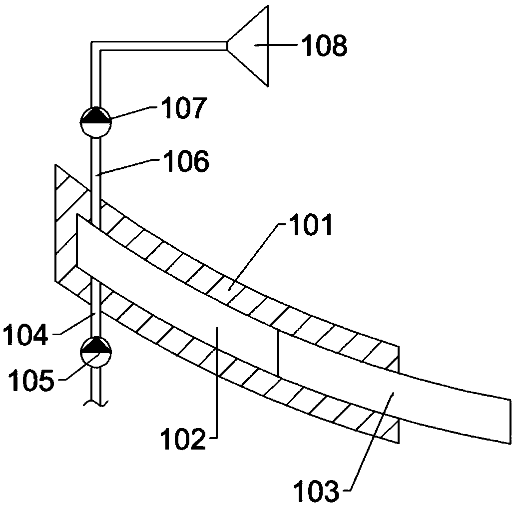
[0030] see figure 1 and image 3 The lower end of the swing rod 8 extends to the inside of the housing 1, and two mixing devices 10 are symmetrically arranged in the housing 1 at the lower end of the swing rod 8, and the mixing device 10 includes a mixing column 101, which is arc-shaped, and One end of the mixing column 101 is fixedly connected to the inner wall of the housing 1, and the mixing column 101 is provided with a groove 102 with an opening facing the side of the swing rod 8. An extrusion column 103 is arranged in the groove 102, and the outer end of the extrusion column 103 It is fixedly connected with the side wall of the swing rod 8; the lower side of the mixing column 101 is connected with a liquid inlet pipeline 104, and the liquid inlet pipeline 104 is provided with a liquid inlet check valve 105; the upper side of the mixing column 101 is connected with a liquid outlet pipeline 106 , the liquid outlet pipe 106 is provided with a liquid outlet one-way valve 10...
Embodiment 3
[0034] see figure 1 and Figure 4 , and two convection devices 11 are symmetrically and fixedly connected to the middle part of the swing rod 8. The convection device 11 includes a fixed rod 111, one end of the fixed rod 111 is fixedly connected to the side wall of the swing rod 8, and the other end of the fixed rod 111 is fixedly connected to a hemispherical shell for installation. Body 112, the inner side wall of the hemispherical shell installation body 112 is evenly arranged with a number of convective protrusions 113, when the liquid material is ejected from the nozzle 108, the swing rod 8 drives the convection device 11 to move to the nozzle 108, the nozzle 108 ejected The liquid material enters the interior of the hemispherical shell mounting body 112, and the liquid material is further mixed under the action of the convective protrusion 113, so that the mixing time of the liquid material is reduced, which has a wide application value.
[0035] The convective protrusio...
PUM
 Abstract
Description
Claims
Application Information
 - R&D
- Intellectual Property
- Life Sciences
- Materials
- Tech Scout
- Unparalleled Data Quality
- Higher Quality Content
- 60% Fewer Hallucinations
Browse by: Latest US Patents, China's latest patents, Technical Efficacy Thesaurus, Application Domain, Technology Topic, Popular Technical Reports.
© 2025 PatSnap. All rights reserved.Legal|Privacy policy|Modern Slavery Act Transparency Statement|Sitemap|About US| Contact US: help@patsnap.com