Temperature control protection drive circuit for LED bulb lamp

A LED bulb lamp, temperature control and protection technology, applied in the field of drive circuit, can solve the problems of high price and complex structure, and achieve the effect of reducing heat generation

Pending Publication Date: 2018-11-20
ZHEJIANG SUNSHINE MEIJIA LIGHTING CO LTD +1
View PDF8 Cites 0 Cited by
  • Summary
  • Abstract
  • Description
  • Claims
  • Application Information

AI Technical Summary

Problems solved by technology

Although it effectively prevents the LED light source and drive power from overheating, the temperature protection circuit uses a temperature detection and control circuit and a complex peripheral control circuit, the structure is relatively complex, and the price is high.

Method used


Image

  • Temperature control protection drive circuit for LED bulb lamp
  • Temperature control protection drive circuit for LED bulb lamp

Examples


Embodiment Construction

[0015] The present invention will be further described in detail below in conjunction with the accompanying drawings and embodiments.

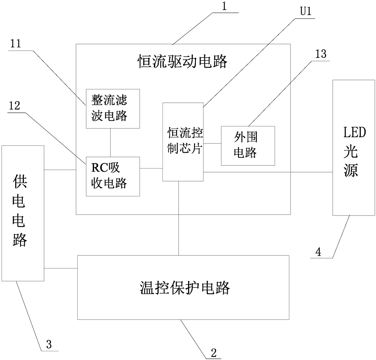
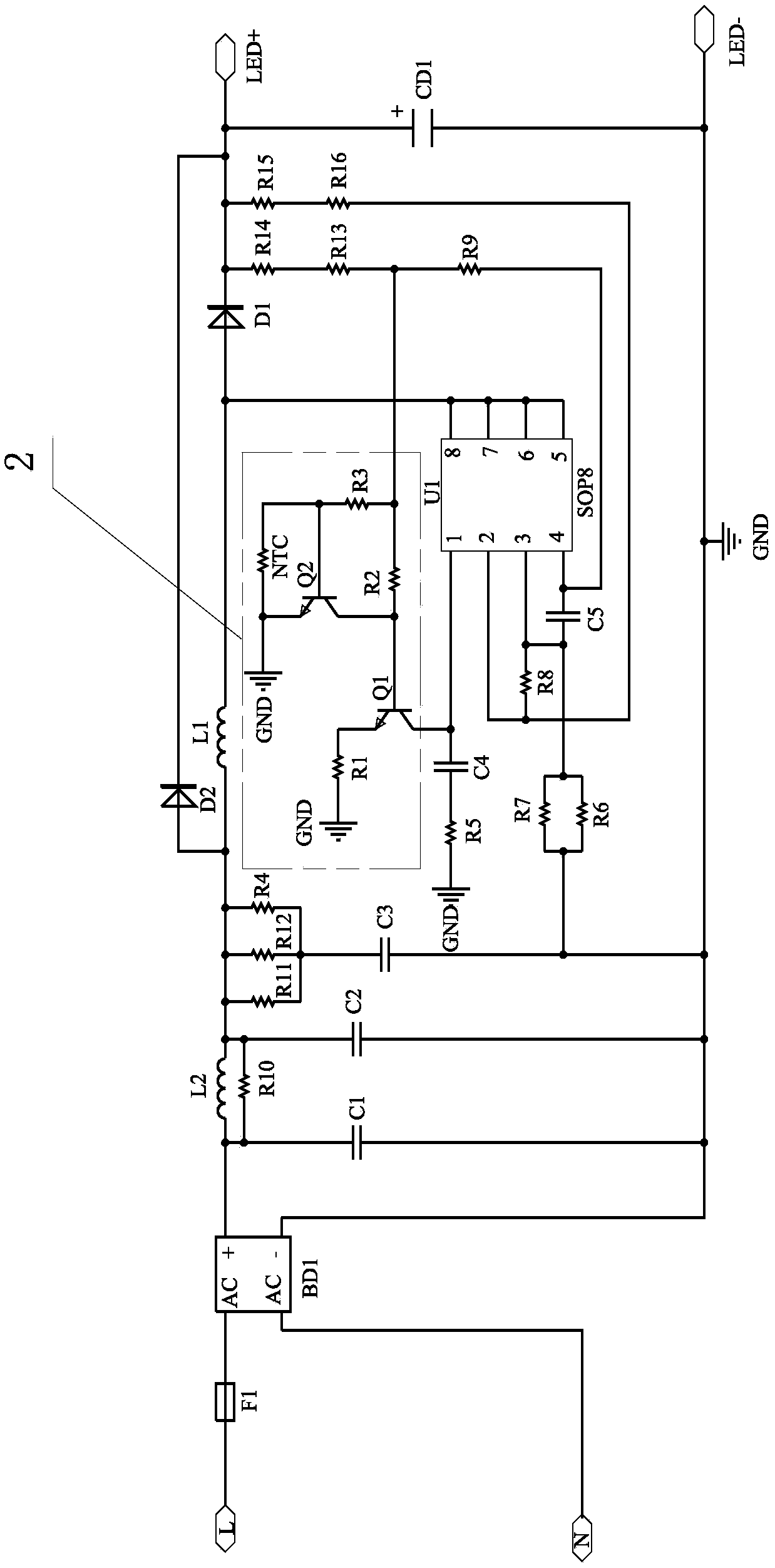
[0016] A temperature control and protection drive circuit for LED bulbs proposed by the present invention, as shown in the figure, includes a constant current drive circuit 1, a temperature control protection circuit 2 and a power supply for the constant current drive circuit 1 and the temperature control protection circuit 2 Power supply circuit 3, constant current drive circuit 1 adopts conventional BOOST constant current boost circuit, constant current drive circuit 1 is composed of rectification filter circuit 11, RC absorption circuit 12, constant current control chip U1 and peripheral circuit 13, temperature control protection circuit 2 Composed of the first triode Q1, the second triode Q2, the negative temperature coefficient thermistor NTC, the first resistor R1, the second resistor R2 and the third resistor R3, the negative temperature...


PUM


Abstract

The invention discloses a temperature control protection drive circuit for an LED bulb lamp. The temperature control protection drive circuit comprises a constant-current drive circuit, a temperaturecontrol protection circuit and a power supply circuit, wherein the constant-current drive circuit is provided with a constant-current control chip; the temperature control protection circuit comprisesa first triode, a second triode, a negative temperature coefficient thermistor, a first resistor, a second resistor and a third resistor; the negative temperature coefficient thermistor is arranged on an LED light source or a drive power supply; a collector of the first triode is connected with a compensation end of the constant-current control chip, an emitter is grounded through the first resistor and a base is connected with the collector of the second triode and one end of the second resistor separately; the other end of the second resistor is connected with one end of the third resistor;a common connection end of the third resistor is connected with the power supply circuit; the other end of the third resistor is connected with the base of the second triode and one end of the negative temperature coefficient thermistor separately; and the other end of the negative temperature coefficient thermistor is connected with the emitter of the second triode and is grounded. The temperature control protection drive circuit has the advantages of being simple in structure and low in cost.

Description

technical field [0001] The invention relates to a driving circuit for an LED lamp, in particular to a temperature control and protection driving circuit for an LED bulb lamp. Background technique [0002] With the in-depth development of national energy conservation and emission reduction and the maturity of LED technology, LED has gradually replaced traditional incandescent and fluorescent lamps and has been widely used in ordinary people's family life. LED bulbs are the most widely used because of their similar appearance to traditional incandescent lamps, simple structure and low price. [0003] Existing LED bulb lamps generally include a light-transmitting cover, an LED light source board, a driving power supply, a lamp body, and a lamp cap. On the narrow mouth end of the lamp body, the driving power is installed inside the lamp body, the LED light source board is installed on the wide mouth end of the lamp body, and the light transmission cover is connected to the wide...

Claims


Application Information

Patent Timeline
Patent Type & Authority Applications(China)
IPC IPC(8): H05B33/08H05B44/00
CPCH05B45/50Y02B20/30
Inventor 王继博徐泉江江琦钟玲祥李阳
Owner ZHEJIANG SUNSHINE MEIJIA LIGHTING CO LTD
Why Eureka
Try Eureka