
Heat-dissipating power distribution cabinet for electric equipment

A heat-dissipating technology for electrical equipment, applied in the field of heat-dissipating power distribution cabinets for electrical equipment, can solve problems such as incomplete heat dissipation and equipment aging, and achieve the effects of increasing the level of height, facilitating movement, and improving practicability

Inactive Publication Date: 2018-11-20
王晓宇
View PDF6 Cites 2 Cited by
  • Summary
  • Abstract
  • Description
  • Claims
  • Application Information

AI Technical Summary

Problems solved by technology

[0003] In order to overcome the problem that the ordinary power distribution cabinet is in use, the internal electrical equipment will generate a large amount of heat when it is energized for a long time, resulting in accelerated aging of the equipment. There are several heat dissipation holes on the cabinet, which cannot completely solve the problem of heat dissipation. The technical problem to be solved by the present invention is to provide a heat dissipation type power distribution cabinet for electrical equipment that can be easily moved and has sufficient heat dissipation

Method used


Image

  • Heat-dissipating power distribution cabinet for electric equipment
  • Heat-dissipating power distribution cabinet for electric equipment
  • Heat-dissipating power distribution cabinet for electric equipment

Examples


Embodiment

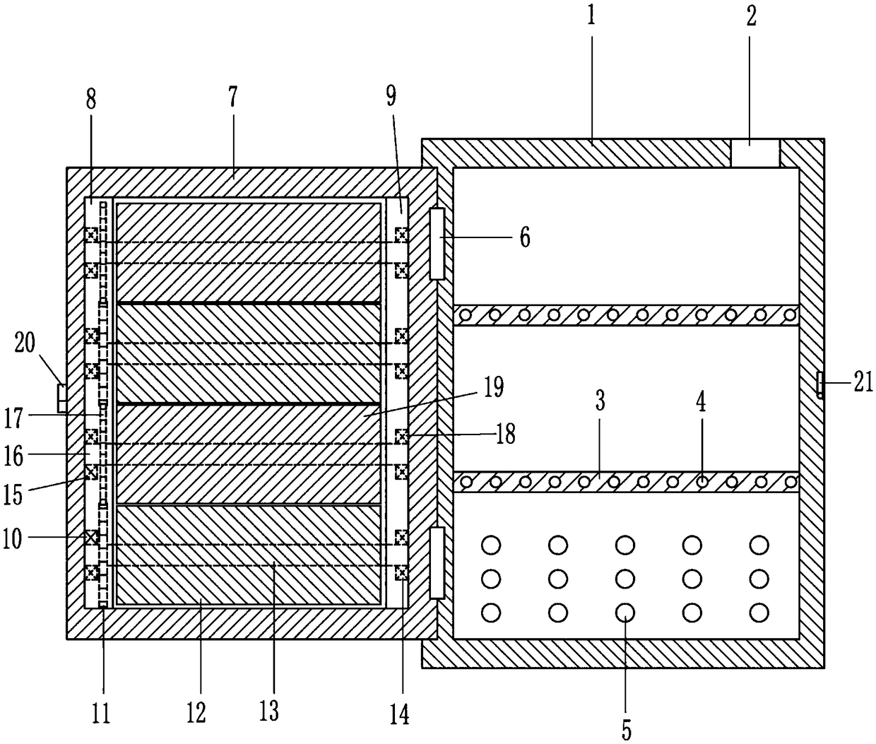
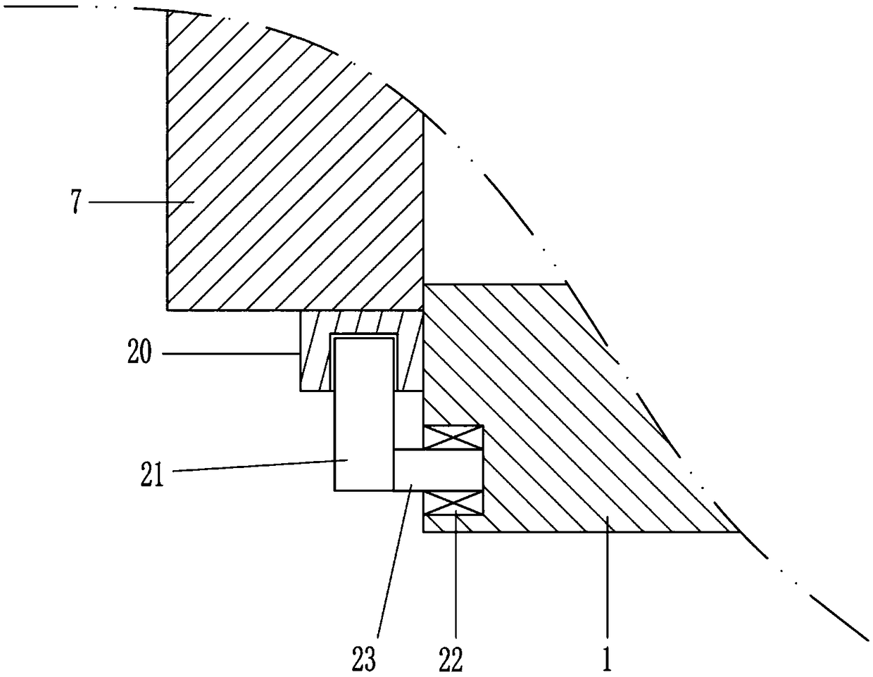
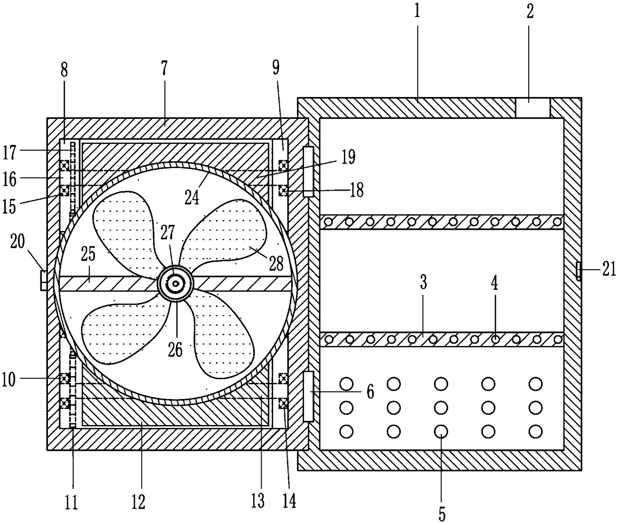
[0024] A cooling type power distribution cabinet for electrical equipment, such as Figure 1-8 As shown, it includes an electrical box 1, a mounting frame 3, a first hinged frame 6, an opening and closing frame 7, a first bearing seat 10, a first gear 11, a first opening and closing leaf 12, a first rotating shaft 13, and a third bearing Seat 15, third bearing seat 15, second rotating shaft 16, second gear 17, fourth bearing seat 18, second opening and closing leaf 19, clamping groove body 20, clamping rod 21, fifth bearing seat 22 and third Rotating shaft 23; the top of the electrical box 1 is provided with an inlet 2 connected to the power supply line; the mounting frame 3 is fixedly connected to the inner wall of the electrical box 1 in turn, and the mounting frame 3 is evenly provided with mounting holes 4 for connecting electrical equipment; the electrical box 1. The inner wall is evenly provided with cooling holes 5 for cooling electrical equipment; the first hinged fram...


PUM


Abstract

The invention relates to the field of electric equipment, in particular to a heat-dissipating power distribution cabinet for the electric equipment and aims at solving the technical problem of providing the heat-dissipating power distribution cabinet for the electric equipment, which can be convenient to move and full in heat dissipation. The heat-dissipating power distribution cabinet for the electric equipment comprises an electric box, mounting racks, first hinged frames, an open and close frame, first bearing blocks, first gears and the like, wherein a wire inlet communicating with a powersupply line is formed in the top in the electric box; the mounting racks are fixedly connected with an inner wall of the electric box in sequence; mounting holes connected with the electric equipmentare uniformly formed in each mounting rack; heat dissipation holes for heat dissipation of the electric equipment are uniformly formed in the inner wall of the electric box; the first hinged frames are fixedly connected with an outer wall of the electric box; the open and close frame is hinged with the first hinged frames; a first mounting groove is formed in an inner side wall of the open and close frame; and a second mounting groove is formed in the other inner side wall. The heat-dissipating power distribution cabinet for the electric equipment has the effects of being convenient to move and full in heat dissipation.

Description

technical field [0001] The invention relates to the field of electrical equipment, in particular to a heat dissipation type distribution cabinet for electrical equipment. Background technique [0002] The power distribution cabinet is the final equipment of the power distribution system. The power distribution cabinet is the general name of the motor control center. The power distribution cabinet is used in the occasions where the load is relatively scattered and there are few circuits; the motor control center is used in the occasions where the load is concentrated and there are many circuits. The electrical energy distributed to the nearest load, this level of equipment should provide protection, monitoring and control of the load. When the ordinary power distribution cabinet is in use, there are a large number of electrical equipment installed inside it. Due to the different resistance values ​​contained in different electrical equipment, a large amount of heat will be g...

Claims


Application Information

Patent Timeline
Patent Type & Authority Applications(China)
IPC IPC(8): H02B1/56H02B1/30
CPCH02B1/565H02B1/303
Inventor 王晓宇
Owner 王晓宇
Learn More