
Material arch breaking system, arch breaking method and discharging bin with material arch breaking system

A silo and material technology, applied in the direction of containers, packaging, transportation and packaging, can solve problems such as poor applicability, complex structure, affecting production progress, etc., to reduce damage and reduce energy consumption.

Pending Publication Date: 2018-11-20
GUANGXI ROAD & BRIDGE ENG GRP CO LTD
View PDF1 Cites 6 Cited by
  • Summary
  • Abstract
  • Description
  • Claims
  • Application Information

AI Technical Summary

Problems solved by technology

However, the silo unclogging device uses a combination of scraper and airflow impact to clear the blockage, and the structure is complex; because it cannot judge the position of the arch, in order to ensure that the cleaning can occur at any position on the inner surface of the silo The movement range of the scraper covers the entire inner surface of the reduced diameter section. When the material is filled in the silo, the movement of the scraper is very difficult, and it is necessary to provide a lot of power to drive the scraper. For large the volume of the silo, its applicability is poor
In addition, it only controls the scraper part and the compressed gas part to carry out the arch breaking operation when it detects that the flow at the discharge port is cut off. During this process, the feeding of the silo is interrupted, which affects the progress of production.

Method used


Image

  • Material arch breaking system, arch breaking method and discharging bin with material arch breaking system
  • Material arch breaking system, arch breaking method and discharging bin with material arch breaking system
  • Material arch breaking system, arch breaking method and discharging bin with material arch breaking system

Examples


Embodiment Construction

[0029] The following will clearly and completely describe the technical solutions in the embodiments of the present invention with reference to the accompanying drawings in the embodiments of the present invention. Obviously, the described embodiments are only some, not all, embodiments of the present invention. Based on the embodiments of the present invention, all other embodiments obtained by persons of ordinary skill in the art without making creative efforts belong to the protection scope of the present invention.

[0030] It should be noted that when a component is said to be "fixed" to another component, it can be directly on the other component or there can also be an intervening component. When a component is said to be "connected" to another component, it may be directly connected to the other component or there may be intervening components at the same time. When a component is said to be "set on" another component, it may be set directly on the other component or t...


PUM


Abstract

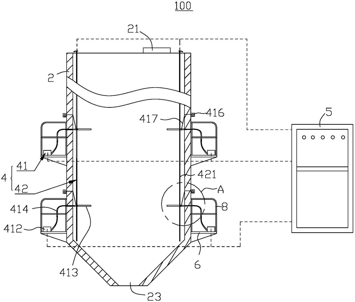
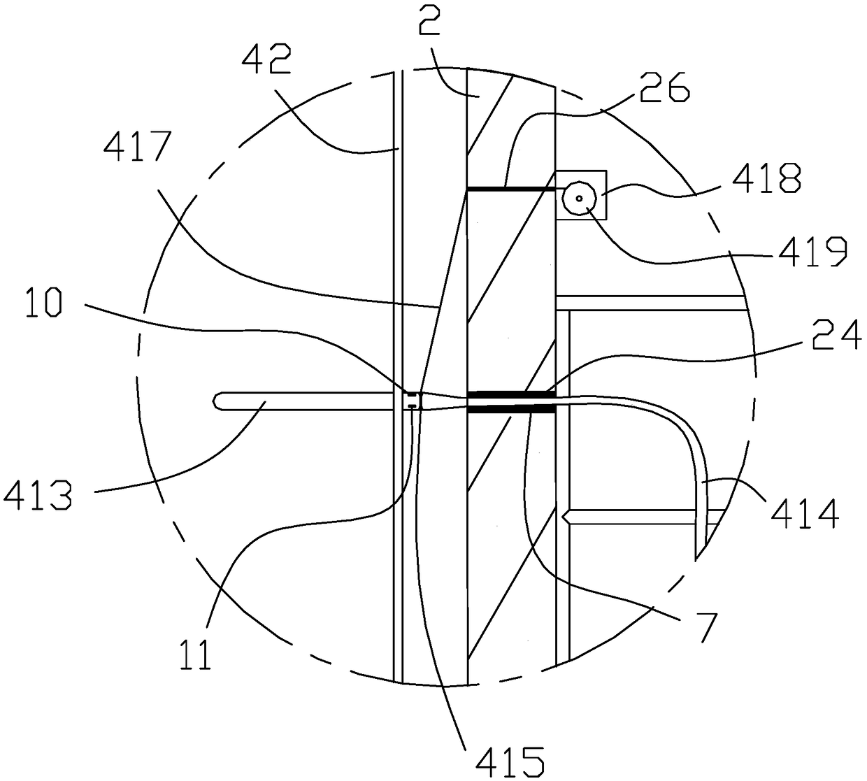
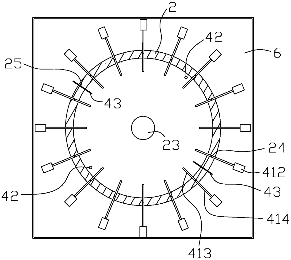
The invention provides a material arch breaking system. The material arch breaking system comprises a plurality of vibrators, at least one level meter, a plurality of material level switches and a controller; the plurality of sets of vibrators are divided into a plurality of groups, the plurality of sets of vibrators are distributed at intervals in the height direction of a material bin, and eachset of vibrators is arranged at intervals around the periphery of the material bin; the material level meter is arranged on the material bin and used for detecting the height of the material level inthe material bin; the material level switches are used for being arranged on the material bin, the plurality of material level switches are divided into a plurality of groups by corresponding to a plurality of sets of vibrators, each set of the material level switches is located below the corresponding group of vibrators or in the same plane as the corresponding group of vibrators, and is used fordetecting the height of the material in the material bin, and materials do not exist in the empty height range; and the material level switches and the vibrators are connected with the controller. According to the material arch breaking system, the arch breaking can be performed for the arch position, the arch breaking effect is good, and the energy consumption can be reduced. The invention further provides an arch breaking method of the material arch breaking system and a discharging bin with the material arch breaking system.

Description

technical field [0001] The invention relates to the technical field of arch breaking, in particular to a material arch breaking system, a method for breaking arches and a discharge bin provided with the material arch breaking system. Background technique [0002] In the construction of large cement or asphalt concrete mixing plants, in order to save storage land, it is beneficial to implement loading and unloading mechanization and automation, reduce labor intensity, improve production efficiency, reduce material loss and dust pollution to the environment, and silos are usually used for storage. materials. The silo is usually built with reinforced cement concrete, and the structure is strong and durable. In the actual construction and production process, the materials stored in the silo are automatically dropped and discharged by their own weight. Due to the influence of water content and friction on the inner wall of the silo, the materials will often arch and fail to pass...

Claims


Application Information

Patent Timeline
IPC IPC(8): B65D88/66
CPCB65D88/66
Inventor 邹晨邢俊平卢振龙韦雪健
Owner GUANGXI ROAD & BRIDGE ENG GRP CO LTD
Learn More