
Hair dryer

A hair dryer and fan technology, which is applied in the direction of washing hair or scalp devices, hair drying devices, hairdressing equipment, etc., can solve the problems of complex structure and high risk of water leakage in hair dryers, and achieves improved efficiency, improved hair care effects, and optimized internal space. Effect

Active Publication Date: 2018-11-20
LESHOW ELECTRONICS TECH CO LTD +1
View PDF7 Cites 0 Cited by
  • Summary
  • Abstract
  • Description
  • Claims
  • Application Information

AI Technical Summary

Problems solved by technology

[0004] However, in this related art, it is necessary to install a water storage device and a liquid supply device inside the hair dryer, resulting in a complicated structure; moreover, due to the existence of the water storage device and the liquid supply device, the risk of water leakage of the hair dryer is high

Method used


Image

  • Hair dryer
  • Hair dryer
  • Hair dryer

Examples


Embodiment Construction

[0038] Reference will now be made in detail to the exemplary embodiments, examples of which are illustrated in the accompanying drawings. When the following description refers to the accompanying drawings, the same numerals in different drawings refer to the same or similar elements unless otherwise indicated. The implementations described in the following exemplary examples do not represent all implementations consistent with the present disclosure. Rather, they are merely examples of apparatuses and methods consistent with aspects of the present disclosure as recited in the appended claims.

[0039] The terminology used in the present disclosure is for the purpose of describing particular embodiments only, and is not intended to limit the present disclosure. As used in this disclosure and the appended claims, the singular forms "a", "the", and "the" are intended to include the plural forms as well, unless the context clearly dictates otherwise. It should also be understood...


PUM


Abstract

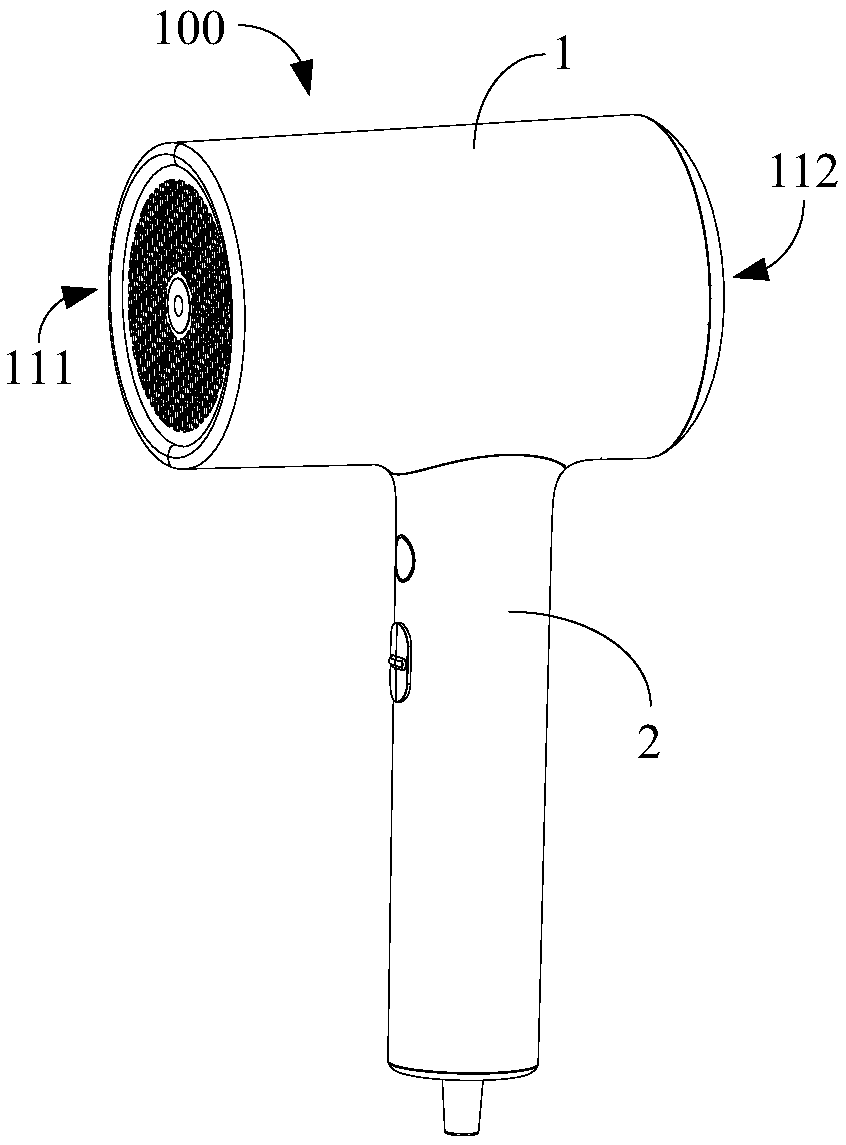
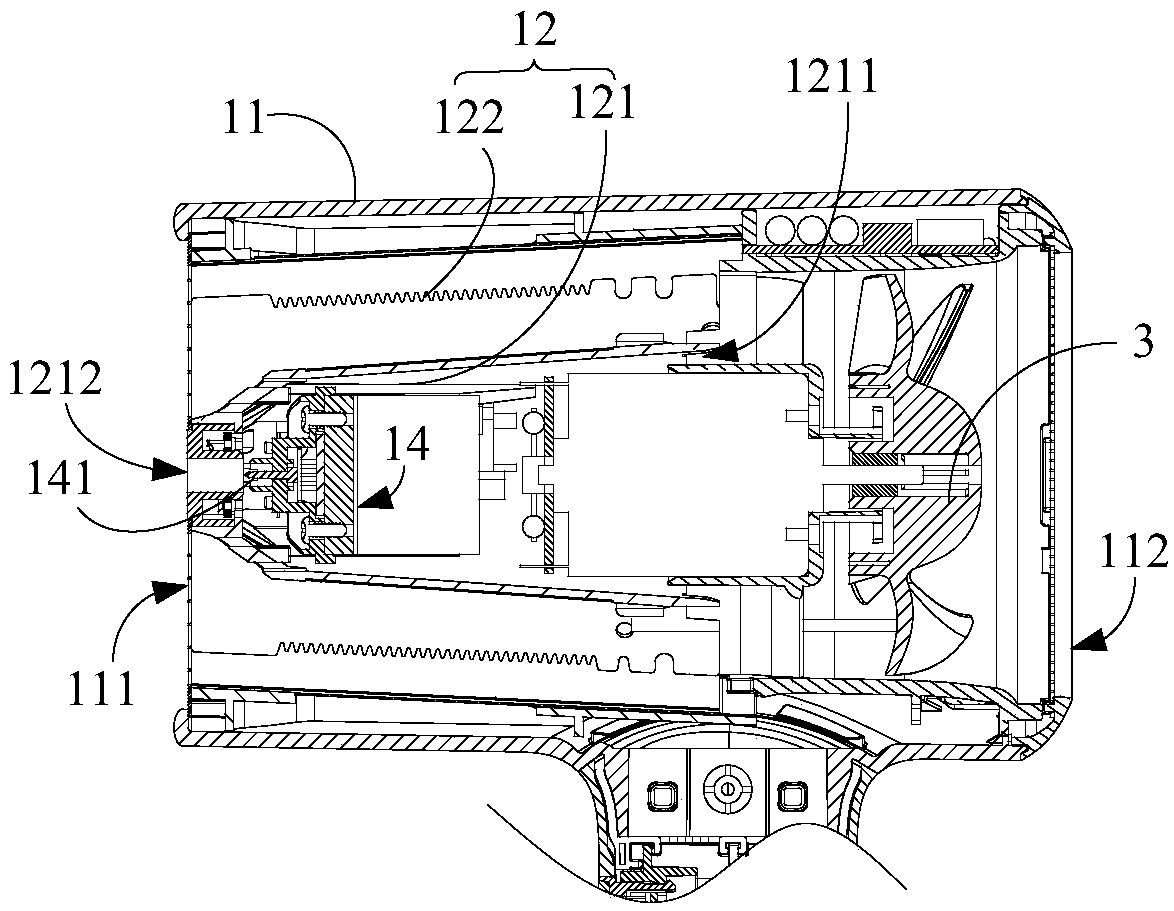
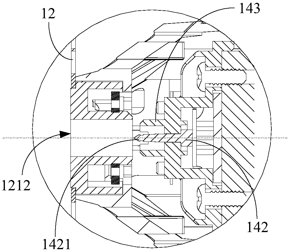
The invention relates to a hair dryer. The hair dryer comprises a main body assembly and a handle assembly connected with the main body assembly; the main body assembly comprises a shell, a heating assembly arranged in the shell, and a fan unit, and the shell comprises an air outlet; the main body assembly further comprises a water ion assembly, and the water ion assembly comprises a condensing device; the heating assembly comprises a heat insulating cylinder and a heat generating unit arranged around the heat insulating cylinder, the condensing device is located in the heat insulating cylinder, the heat insulating cylinder is provided with an airflow inlet through which airflow generated by the fan unit enters the heat insulating cylinder, and the airflow inlet is located in the upstreampart of the heat generating unit.

Description

technical field [0001] The present disclosure relates to the technical field of household appliances, in particular to a hair dryer. Background technique [0002] Based on the characteristics of rapid styling and drying of hair dryers, it has a large audience. The motor in the hair dryer can suck airflow from the air inlet of the hair dryer, and send the sucked airflow out from the air outlet opposite to the air inlet, so as to achieve the purpose of styling. [0003] In the related technology, if the applicant is Matsushita Electric Works Co., Ltd., and the application number is 200510106452.9 in the patent application document, in order to improve the humidity of the airflow discharged from the air outlet, a container for storing liquid, a liquid supply pipe and mist can be arranged inside the hair dryer. The generating device enables the liquid in the liquid storage container to be transported through the liquid supply pipe, and further generates water mist through the a...

Claims


Application Information

Patent Timeline
Patent Type & Authority Applications(China)
IPC IPC(8): A45D20/12
CPCA45D20/12
Inventor 喻金明肖钊贤吴景
Owner LESHOW ELECTRONICS TECH CO LTD
Learn More