A Novel Low Profile High Gain Vehicle Antenna

A vehicle-mounted antenna and low-profile technology, applied in the field of antennas, can solve the problems of reducing antenna wind resistance, unsatisfactory shark-fin antenna gain, and limiting vehicle-mounted antenna gain, achieving the effect of wide application range and convenient installation

Active Publication Date: 2020-06-05
ZHEJIANG UNIV
View PDF8 Cites 0 Cited by
  • Summary
  • Abstract
  • Description
  • Claims
  • Application Information

AI Technical Summary

Problems solved by technology

Generally speaking, the higher the antenna profile, the better the antenna's gain and other parameters; but in order to reduce air resistance, the shape of the car is usually streamlined, which limits the parameters such as the profile of the vehicle antenna, which in turn limits the performance of the vehicle antenna such as gain
In order to balance the gain and size of the antenna, the shark fin antenna has been widely used in recent years. Its smooth shape can reduce the wind resistance caused by the protruding antenna to a certain extent, and its higher antenna profile is conducive to accommodate higher gain. antenna, but for the low frequency band, the gain brought by the shark fin antenna is not satisfactory

Method used


Image

  • A Novel Low Profile High Gain Vehicle Antenna
  • A Novel Low Profile High Gain Vehicle Antenna
  • A Novel Low Profile High Gain Vehicle Antenna

Examples


Embodiment Construction

[0024] The present invention will be further described below in conjunction with the accompanying drawings and specific embodiments.

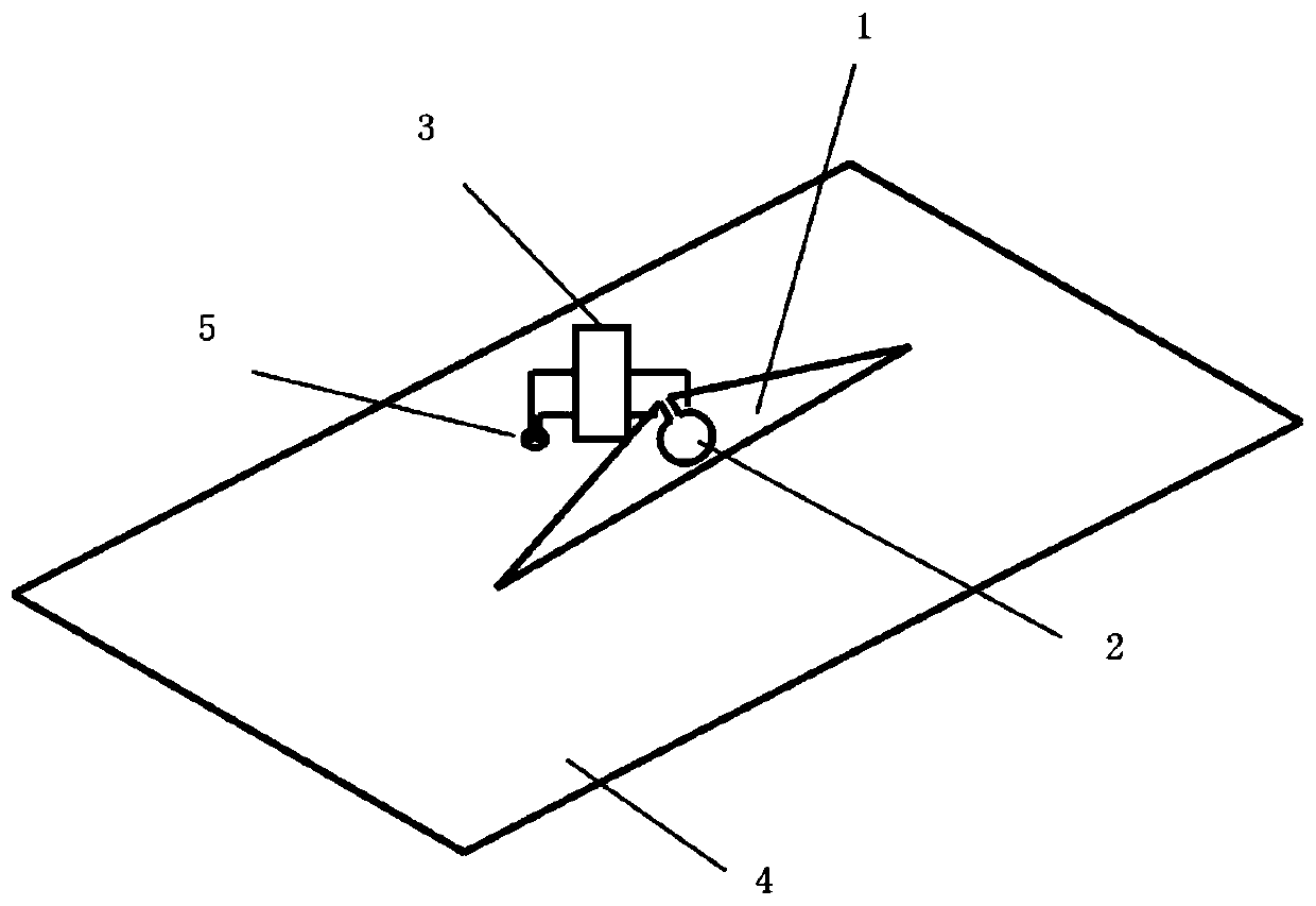
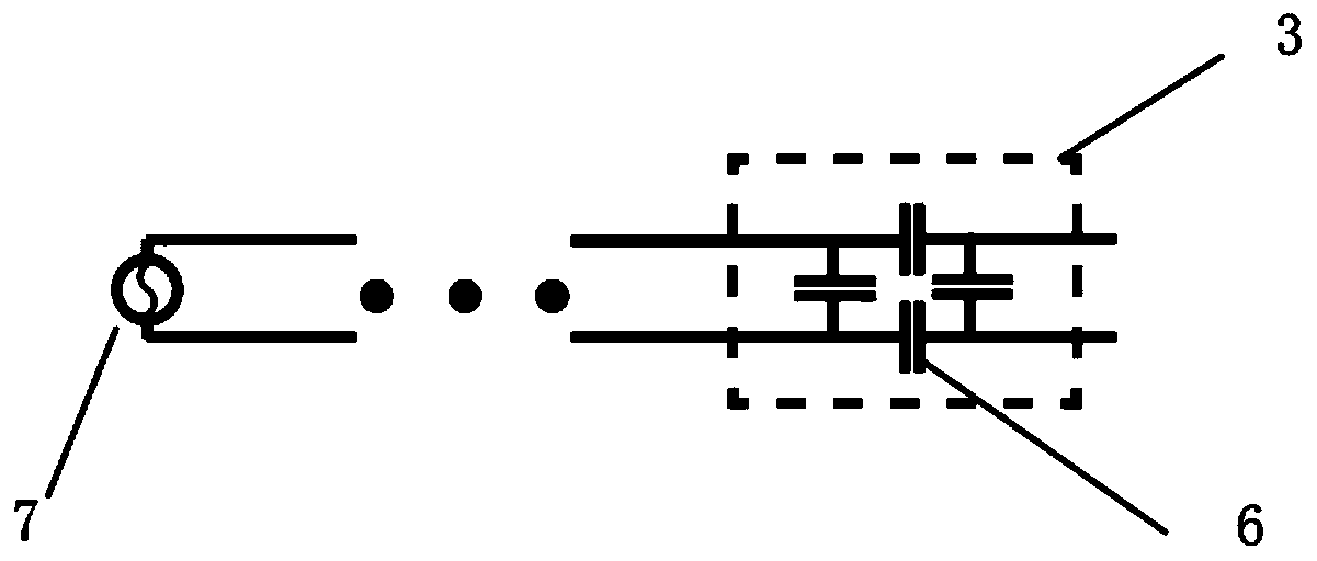
[0025] Such as figure 1 As shown, the present invention comprises a metal layer 1, a matching circuit 3 and an automobile metal casing 4. The metal layer 1 is placed on the automobile metal casing 4 on a vertical horizontal plane. There is an annular gap 2, and the annular gap 2 extends to the top edge of the isosceles trapezoid through both sides of the rectangular through groove, so that the top edge of the isosceles trapezoid is divided into two halves, and the metal layer 1 is connected with the signal source 7 after passing through the matching circuit 3 The matching circuit 3 is connected to the signal source 7 via a parallel feeder.

[0026] The parallel feeder passes through the feeder installation point on the roof of the car and is connected to the signal source 7 inside the car. The feeder installation point is the small hole 5 on t...


PUM


Abstract

The invention discloses a novel low-profile high-gain vehicle-mounted antenna. The vehicle-mounted antenna comprises a metal layer, a matching circuit and an automobile metal shell, wherein an annularnotch is formed in the top edge of the metal layer; the length of the inner ring of the annular notch determines the center frequency of the working frequency interval of the antenna; the metal layeris connected with a signal source after passing through the matching circuit; and the metal layer and the matching circuit are mounted at the top part of the automobile metal shell, so that radiationand collection of signals can be realized by fully utilizing the metal shell. Compared with a traditional shark fin antenna and a glass antenna, the novel low-profile high-gain vehicle-mounted antenna is low in profile, capable of fully utilizing the automobile body as the bottom of the antenna, and higher in gain; the working frequency of the antenna can be adjusted in a large range through a tuning circuit and is not influenced by the structure of the vehicle body, so that the antenna has the advantages of being convenient to install and wide in application range, and can be used for replacing various existing vehicle-mounted communication antennas.

Description

technical field [0001] The invention relates to an antenna, in particular to a novel low-profile high-gain vehicle-mounted antenna. Background technique [0002] With the rapid development of wireless communication, the antenna, as the carrier of signal transmission and reception, has an important application in wireless communication. With the continuous improvement of the performance of the wireless communication system, the communication industry puts forward a series of requirements for antenna design such as high gain, miniaturization and low cost. [0003] As an important medium for communication between people in the car and the outside world, the performance of the car antenna directly affects the communication quality. Generally speaking, the higher the antenna profile, the better the antenna's gain and other parameters; but in order to reduce air resistance, the shape of the car is usually streamlined, which limits the parameters such as the profile of the vehicle...

Claims


Application Information

Patent Timeline
Patent Type & Authority Patents(China)
IPC IPC(8): H01Q23/00H01Q1/32H01Q1/44H01Q1/36H01Q1/50
CPCH01Q1/3275H01Q1/36H01Q1/44H01Q1/50H01Q23/00
Inventor 马超皇甫江涛
Owner ZHEJIANG UNIV
Why Eureka
Try Eureka