Angle sensor test device

An angle sensor and testing device technology, applied in the direction of measuring devices, electrical devices, instruments, etc., can solve the problems of quick disassembly, input shaft damage, measurement accuracy and single function, and achieve accurate and efficient locking and separation, and rapid positioning Locking and dismounting, testing the effect of high precision

Inactive Publication Date: 2018-11-16
HUBEI SANJIANG AEROSPACE HONGFENG CONTROL
View PDF13 Cites 0 Cited by
  • Summary
  • Abstract
  • Description
  • Claims
  • Application Information

AI Technical Summary

Problems solved by technology

Although the structure of the angle sensor accuracy test device disclosed in this patent is relatively simple, its measurement accuracy and functions are relatively single, which cannot meet the current angle sensor accuracy requirements, especially the test device is still unable to position and lock the product under test. Disassembly, disassembly and assembly of the test device may cause damage to the input shaft of the product under test, and the operation is inconvenient

Method used


Image

  • Angle sensor test device
  • Angle sensor test device
  • Angle sensor test device

Examples


Embodiment Construction

[0026] In order to make the object, technical solution and advantages of the present invention clearer, the present invention will be further described in detail below in conjunction with the accompanying drawings and embodiments. It should be understood that the specific embodiments described here are only used to explain the present invention, not to limit the present invention.

[0027] In addition, the technical features involved in the various embodiments of the present invention described below may be combined with each other as long as they do not constitute a conflict with each other.

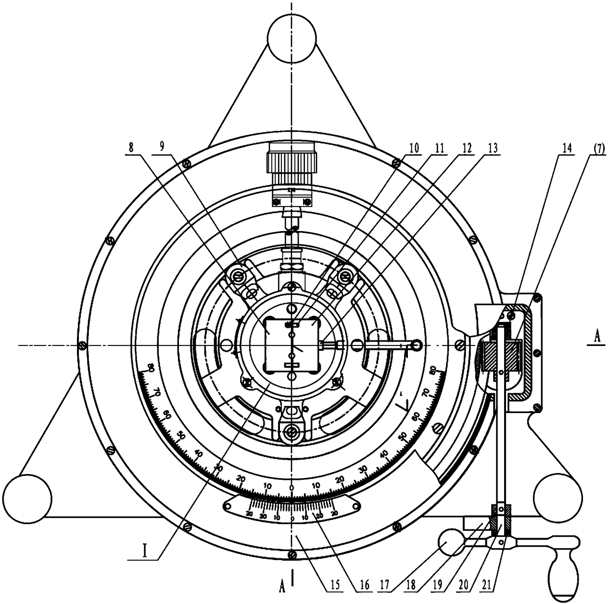
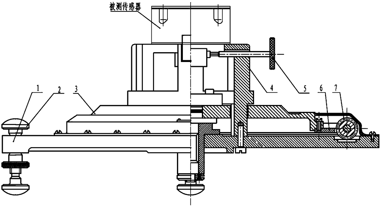
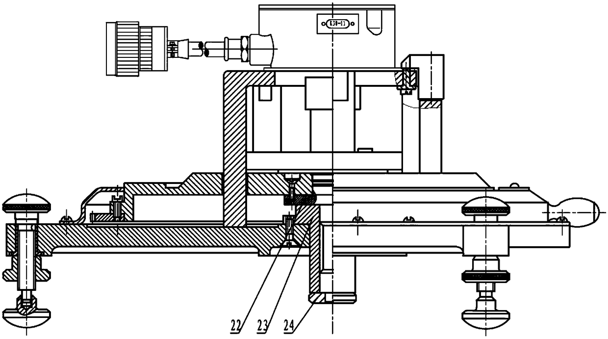
[0028] figure 1 It is an assembly front view of the test device of the embodiment of the present invention; figure 2 yes figure 1 A cross-sectional view in one direction of ; image 3 yes figure 1 A cross-sectional view in the other direction of ; Figure 4 yes figure 1 Partial enlarged view of the input shaft pressing block part.

[0029] Such as figure 1 As shown in , the ang...


PUM


Abstract

The invention discloses an angle sensor test device comprising: a base; a turbine disposed on the surface of the base; a rotating disc disposed coaxially with the turbine and capable of rotating coaxially under the rotation of the turbine; a hollow cylindrical fixing bracket having one end passing through an annular groove on the rotating disc to be fixed to the surface of the base and other end used for mounting and supporting an angle sensor to be tested; a rotating bracket disposed on the upper end of a central rotating shaft, capable of synchronously rotating with the central rotating shaft, and including a mounting plate located at the top and having a half hole on one side thereof; and an input shaft pressing block opposite to the rotating bracket and having a corresponding half holeon the opposite side. The corresponding half holes can form a complete hole when the opposite sides of the input shaft pressing block and the rotating bracket come into contact with each other in order that an input shaft can be inserted into the complete hole and clamped. The angle sensor test device can lock and quickly disassemble a tested product under the premise of ensuring the test precision, and does not cause damage to the input shaft of the tested product.

Description

technical field [0001] The invention belongs to the technical field of angle sensors, and more specifically relates to an angle sensor testing device. Background technique [0002] The angle sensor is a component that converts the rotation angle into an electrical signal. In the steering gear product, the angle sensor is an indispensable sensor in the closed-loop rudder system. The working principle of the angle sensor is generally that the input shaft of the angle sensor is driven by the measured rotating shaft to rotate, and the input shaft of the angle sensor drives the contact of the sliding rheostat to rotate relative to the resistance wire to change the resistance of the angle sensor, thereby realizing the rotation of the measured rotating shaft The function of converting the angle into an electrical signal achieves the purpose of measuring the angle. [0003] The angle sensor needs to be tested for items such as zero adjustment and linearity during the production pro...

Claims


Application Information

Patent Timeline
Patent Type & Authority Applications(China)
IPC IPC(8): G01B7/30
CPCG01B7/30G01B21/042
Inventor 段友明徐秀忠樊贺斌刘成强宋超凡渠向东王浩洲陈竹宁李畅
Owner HUBEI SANJIANG AEROSPACE HONGFENG CONTROL
Why Eureka
Try Eureka