Rotary cotton collecting machine
A cotton collector and rotary technology, applied in the field of cotton collectors, can solve the problems of unsightly finished products, labor-intensive, unfavorable processing, etc., and achieve the effects of increasing the service life, saving manpower, and reducing the number of people
- Summary
- Abstract
- Description
- Claims
- Application Information
AI Technical Summary
Problems solved by technology
Method used
Image

Examples
Embodiment 1
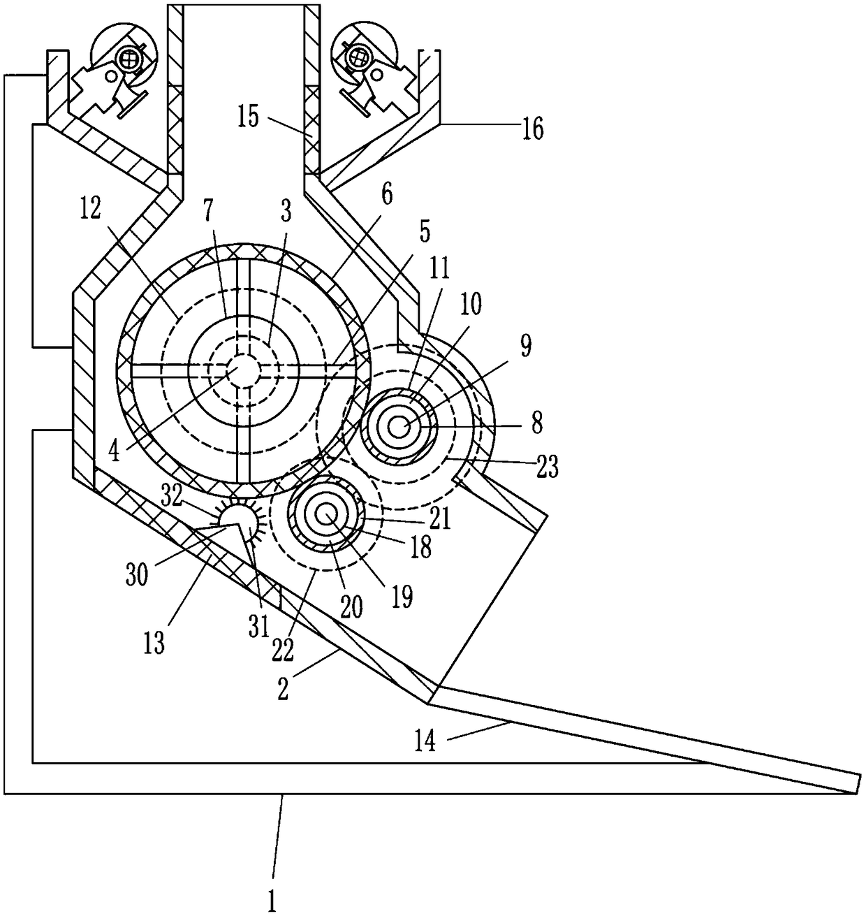
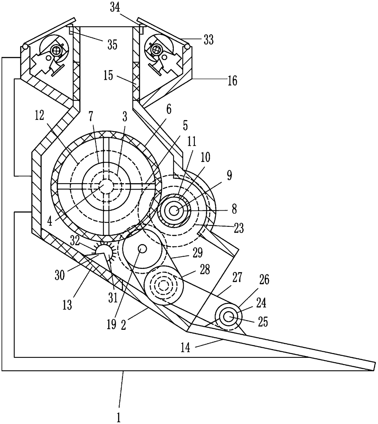
[0020] A rotary cotton collector, such as Figure 1-2 As shown, it includes frame 1, cotton collecting tube 2, left bearing seat 3, left turning rod 4, connecting rod 5, cylindrical screen 6, deceleration motor 7, right bearing seat 8, right turning rod 9, upper cylinder Shaped drum 10, elastic sleeve 11, large gear 12, lower screen plate 13, inclined plate 14, upper plate 15, mounting plate 16 and blower fan 17, the middle part of the right side of frame 1 is connected with cotton collecting tube 2, cotton collecting tube 2 The middle parts of the front and back walls are embedded with a left bearing seat 3, and a left turning rod 4 is connected between the two left bearing seats 3, and four connecting rods 5 are uniformly connected on the left turning rod 4, and the outer ends of the connecting rods 5 are connected with Cylindrical screen 6, a reduction motor 7 is installed in the middle of the front side of the cotton collecting cylinder 2, the output shaft of the reducing ...
Embodiment 2
[0022] A rotary cotton collector, such as Figure 1-2As shown, it includes frame 1, cotton collecting tube 2, left bearing seat 3, left turning rod 4, connecting rod 5, cylindrical screen 6, deceleration motor 7, right bearing seat 8, right turning rod 9, upper cylinder Shaped drum 10, elastic sleeve 11, large gear 12, lower screen plate 13, inclined plate 14, upper plate 15, mounting plate 16 and blower fan 17, the middle part of the right side of frame 1 is connected with cotton collecting tube 2, cotton collecting tube 2 The middle parts of the front and back walls are embedded with a left bearing seat 3, and a left turning rod 4 is connected between the two left bearing seats 3, and four connecting rods 5 are uniformly connected on the left turning rod 4, and the outer ends of the connecting rods 5 are connected with Cylindrical screen 6, a reduction motor 7 is installed in the middle of the front side of the cotton collecting cylinder 2, the output shaft of the reducing m...
Embodiment 3
[0025] A rotary cotton collector, such as Figure 1-2 As shown, it includes frame 1, cotton collecting tube 2, left bearing seat 3, left turning rod 4, connecting rod 5, cylindrical screen 6, deceleration motor 7, right bearing seat 8, right turning rod 9, upper cylinder Shaped drum 10, elastic sleeve 11, large gear 12, lower screen plate 13, inclined plate 14, upper plate 15, mounting plate 16 and blower fan 17, the middle part of the right side of frame 1 is connected with cotton collecting tube 2, cotton collecting tube 2 The middle parts of the front and back walls are embedded with a left bearing seat 3, and a left turning rod 4 is connected between the two left bearing seats 3, and four connecting rods 5 are uniformly connected on the left turning rod 4, and the outer ends of the connecting rods 5 are connected with Cylindrical screen 6, a reduction motor 7 is installed in the middle of the front side of the cotton collecting cylinder 2, the output shaft of the reducing ...
PUM
 Abstract
Description
Claims
Application Information
 - R&D
- Intellectual Property
- Life Sciences
- Materials
- Tech Scout
- Unparalleled Data Quality
- Higher Quality Content
- 60% Fewer Hallucinations
Browse by: Latest US Patents, China's latest patents, Technical Efficacy Thesaurus, Application Domain, Technology Topic, Popular Technical Reports.
© 2025 PatSnap. All rights reserved.Legal|Privacy policy|Modern Slavery Act Transparency Statement|Sitemap|About US| Contact US: help@patsnap.com