
An auxiliary device for welding the front pillar of the pedal

An auxiliary device and column technology, which is applied in the field of welding auxiliary devices for the front column of the pedal, can solve problems such as lack of clamping adaptability, and achieve the effect of ensuring clamping effect and reasonable structure

Active Publication Date: 2020-03-24
浙江恒源机器有限公司
View PDF5 Cites 0 Cited by
  • Summary
  • Abstract
  • Description
  • Claims
  • Application Information

AI Technical Summary

Problems solved by technology

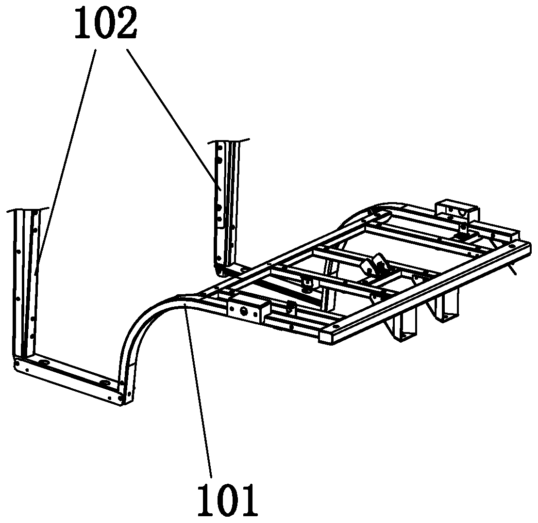
The front frame includes multiple parts, among which the pedal front column and the front seat bracket are all part of the front frame. During the production process of the vehicle, the pedal front column needs to be welded to the front seat bracket. Currently, the pedal front column and the front Although the welding fixture of the seat bracket can realize the clamping function, it is still lacking in clamping adaptability and other aspects

Method used


Image

  • An auxiliary device for welding the front pillar of the pedal
  • An auxiliary device for welding the front pillar of the pedal
  • An auxiliary device for welding the front pillar of the pedal

Examples


Embodiment 1

[0026] Embodiment 1: as figure 2 , image 3 , Figure 4 as shown in

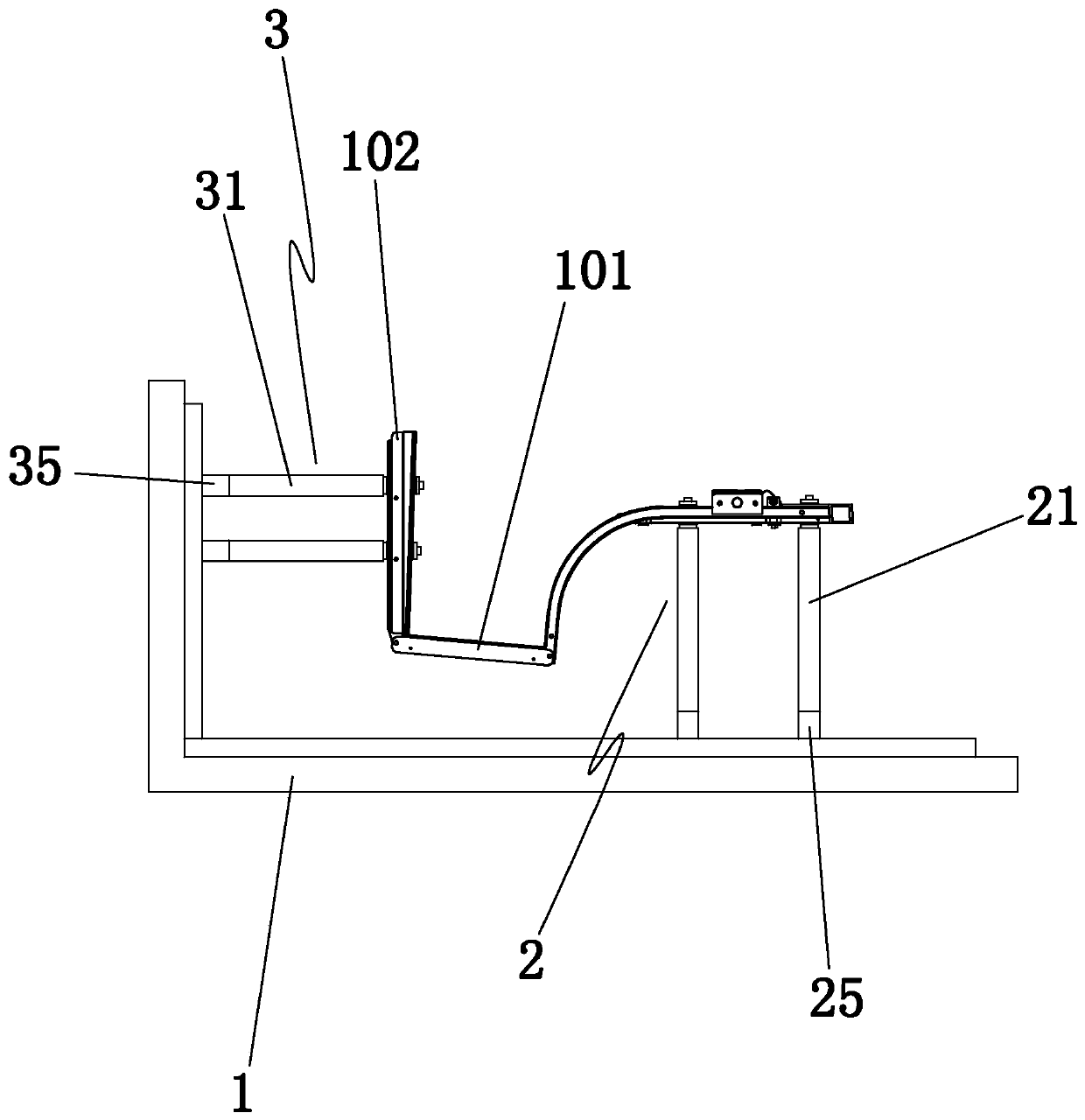
[0027] An auxiliary device for welding the front pillar of the pedal, including

[0028] Main welding platform 1, some front seat bracket locators 2 and some pedal front pillar locators 3;

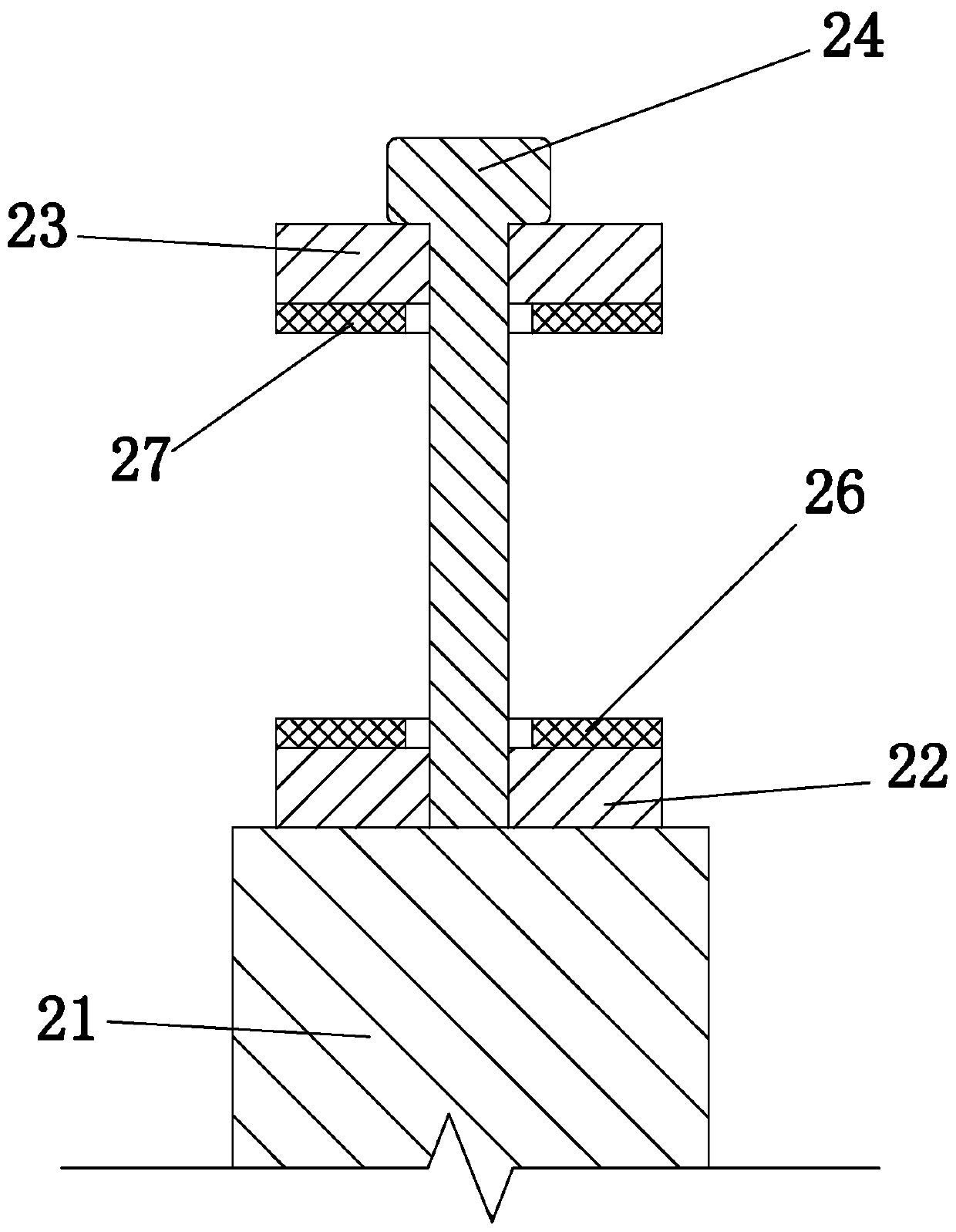
[0029] Described headstock seat bracket locator comprises vertical rod 21, bottom contact plate 22, top contact plate 23 and the vertical screw 24 that is used to compress top contact plate, in a headstock seat bracket locator: vertical bar lower end is provided with The vertical screw rod 25 that is threadedly connected with the main welding platform, the upper end of the vertical rod is connected with the bottom contact plate, the bottom contact plate is between the top contact plate and the vertical rod, the vertical screw passes through the top contact plate and the bottom contact plate, and the vertical screw is connected with the bottom contact plate. Pole threaded connection;

[0030] The front pillar locato...

Embodiment 2

[0034] Embodiment 2: based on embodiment 1, such as Figure 5 , Image 6 as shown,

[0035] It also includes several welding dust cleaning devices. The welding dust cleaning device includes an air pump 4 and an air blowing pipe 5. In one welding dust cleaning device: the outlet of the air pump is connected to the inlet end of the air blowing pipe, and the outlet end of the air blowing pipe faces the corresponding welding position. When welding for a certain welding position, the welding dust cleaning device corresponding to the welding position will blow air to quickly remove the welding dust (hereinafter referred to as impurities) at the welding position.

[0036] The welding dust cleaning device also includes a suction pipe 6 and a blanking pipe 7, the inlet of the air pump is connected to the outlet of the suction pipe, the inlet of the suction pipe is provided with a suction horn tube 8, and the suction end of the suction horn tube faces the corresponding welding positio...


PUM


Abstract

The invention discloses a pedal front stand column welding auxiliary device. The device comprises a plurality of vehicle head seat support locators and a plurality of pedal front stand column positioners, the head seat support positioner comprises a vertical rod, a bottom contact plate, a top contact plate and a vertical screw, the vertical screw rod which is in threaded connection with the main welding platform is arranged at the lower end of the vertical rod, the pedal front stand column positioners comprises a cross rod, an outer contact plate, an inner contact plate and a transverse screw,a cross screw rod which is in threaded connection with the main welding platform is arranged at one end of the cross rod. The device has the beneficial effects that the structure is reasonable, the clamping and positioning of the vehicle head seat bracket and the pedal front stand column can be effectively realized, and so that the clamping effect can be effectively guaranteed.

Description

technical field [0001] The invention belongs to the technical field of vehicle processing, and in particular relates to a welding auxiliary device for a front pillar of a pedal. Background technique [0002] The front frame is an important part of the vehicle. The front frame includes multiple parts, among which the pedal front column and the front seat bracket are all part of the front frame. During the production process of the vehicle, the pedal front column needs to be welded to the front seat bracket. Currently, the pedal front column and the front Although the welding fixture of the seat bracket can realize the clamping function, it is still lacking in clamping adaptability and other aspects. Contents of the invention [0003] The purpose of the present invention is to overcome the deficiencies in the prior art and provide a structure that is reasonable, can effectively realize the clamping and positioning of the front seat bracket and the front pillar of the pedal,...

Claims


Application Information

Patent Timeline
Patent Type & Authority Patents(China)
IPC IPC(8): B23K37/04B23K37/00
CPCB23K37/00B23K37/0443
Inventor 刘桂祥李少良
Owner 浙江恒源机器有限公司
Learn More