
A fire hose automatic cleaning reel device

An automatic cleaning and fire hose technology, applied in fire rescue and other directions, can solve the problem that the hose cannot be cleaned, and achieve the effect of sufficient and complete cleaning, good cleaning effect and good brushing effect.

Active Publication Date: 2020-09-04
张丽华
View PDF6 Cites 0 Cited by
  • Summary
  • Abstract
  • Description
  • Claims
  • Application Information

AI Technical Summary

Problems solved by technology

But it has the following disadvantages: before cleaning, the head end of the water hose needs to be fixed on the reel driven by the stepper motor for winding the water hose, and the reel is located outside the box body, so a part of the side where the head end of the water hose is located Hose cannot be cleaned

Method used


Image

  • A fire hose automatic cleaning reel device
  • A fire hose automatic cleaning reel device
  • A fire hose automatic cleaning reel device

Examples


Embodiment

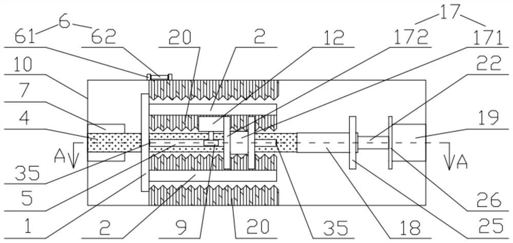
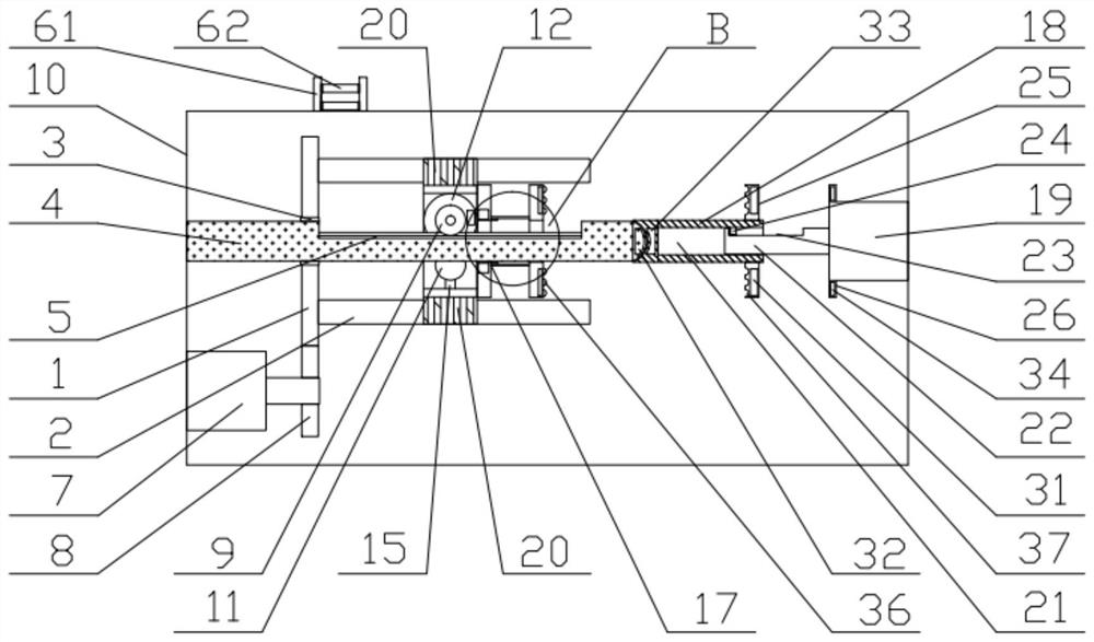
[0034] likefigure 1 and figure 2 A fire hose automatic cleaning reel device shown includes a box body 10 containing water inside. The box body 10 is provided with a cleaning mechanism and a reel mechanism. The cleaning mechanism includes a shaping component, a walking component and a cleaning mechanism. Brush 20;

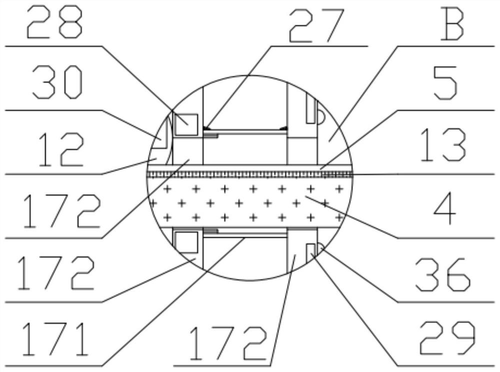
[0035] Described sizing assembly comprises rotating disk 1 and at least three winding rods 2 (such as Figure 5 As shown, three winding rods 2) are provided in this embodiment, and a perforation is provided at the center of the turntable 1, and a fixed shaft 4 is connected to the perforation through a bearing 3 in the perforation, and the fixed shaft 4 is wound on its back. One end of the side where the rod 2 is located is fixed on the inner wall of one end of the box body 10, and the part of the fixed shaft 4 corresponding to the winding rod 2 is provided with a running groove 5 parallel to the axial direction of the fixed shaft 4, and the walking assembly is ins...


PUM


Abstract

The invention discloses an automatic cleaning and reeling device for a fire hose, and belongs to the field of fire protection equipment. The automatic cleaning and reeling device comprises a box bodyinternally containing water. A cleaning mechanism and a reeling mechanism are arranged in the box body. The cleaning mechanism comprises a sizing assembly, a walking assembly and cleaning brushes. Thereeling mechanism comprises an I-shaped winding disc, a rotation shaft and a reeling motor. The sizing assembly comprises a rotary disc and at least three winding rods fixed to the rotary disc. A fixing shaft penetrates the center position of the rotary disc and is provided with a walking groove for the walking assembly to move. A drive gear driven by a rotation motor and externally engaged withthe rotary disc is arranged beside the rotary disc. The cleaning brushes are fixed to the top and the bottom of a forward and reverse rotation motor, the sides, towards the fixing shaft, of the winding rods, and the inner wall of the box body. The I-shaped winding disc sleeves the fixing shaft or the rotation shaft, and the rotation shaft is connected to a drive shaft of the reeling motor througha key groove. The automatic cleaning and reeling device can integrally clean the hose, the cleaning stroke can be increased, cleaning is sufficient and complete, the cleaning effect is good, and watercan be saved as well.

Description

technical field [0001] The invention relates to the field of fire-fighting equipment, in particular to an automatic cleaning reel device for a fire-fighting hose. Background technique [0002] In the field of firefighting equipment, a fire hose is a hose used to transport flame-retardant liquids such as high-pressure water or foam. At the end of each firefighting operation, the fire hose needs to be cleaned and reeled again for transportation and next use. However, in the prior art, the cleaning and reeling of the fire hose is mainly completed by manual operation, which has defects such as high work intensity and low work efficiency. [0003] In the patent with authorized notification number CN 105126285B, a fire hose automatic cleaning device is disclosed, which includes a box body, two stepping motors, a guide rod, a brush, a box cover, a control box, and a battery. The stepper motors are respectively installed at the left and right ends of the box body, one end of the g...

Claims


Application Information

Patent Timeline
Patent Type & Authority Patents(China)
IPC IPC(8): A62C33/02
CPCA62C33/02
Inventor 任冲
Owner 张丽华
Learn More