
Direction reconfigurable antenna

A technology for reconstructing antennas and arcs, which is applied in the directions of antenna grounding device, antenna grounding switch structure connection, radiating element structure, etc. It can solve problems such as increased energy use, limited rated power of electronic devices, and inability to apply in high-power applications. , to achieve the effect of reducing production costs

Inactive Publication Date: 2018-11-13
袁涛
View PDF5 Cites 0 Cited by
  • Summary
  • Abstract
  • Description
  • Claims
  • Application Information

AI Technical Summary

Problems solved by technology

[0003] At present, the commonly used pattern reconfigurable antenna adopts the method of using electronic components to control the switching of the pattern. The disadvantage of this method is that the rated power of the electronic components is limited, and it cannot be applied in high-power occasions, and the electronic components must be Using a bias circuit to provide energy increases energy usage for the overall system

Method used


Image

  • Direction reconfigurable antenna
  • Direction reconfigurable antenna
  • Direction reconfigurable antenna

Examples


Embodiment

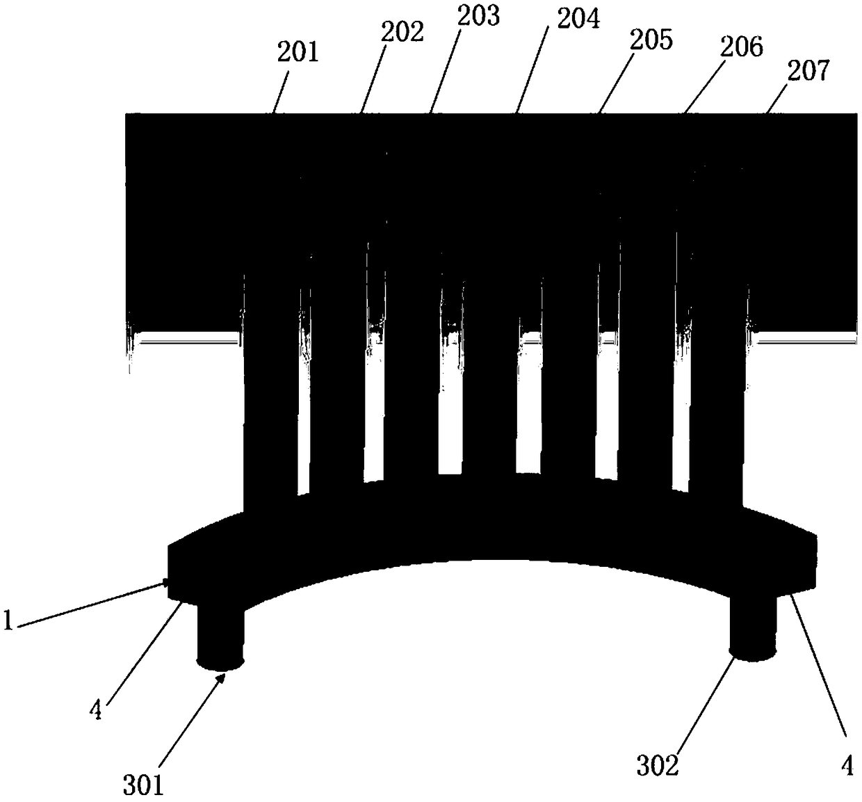
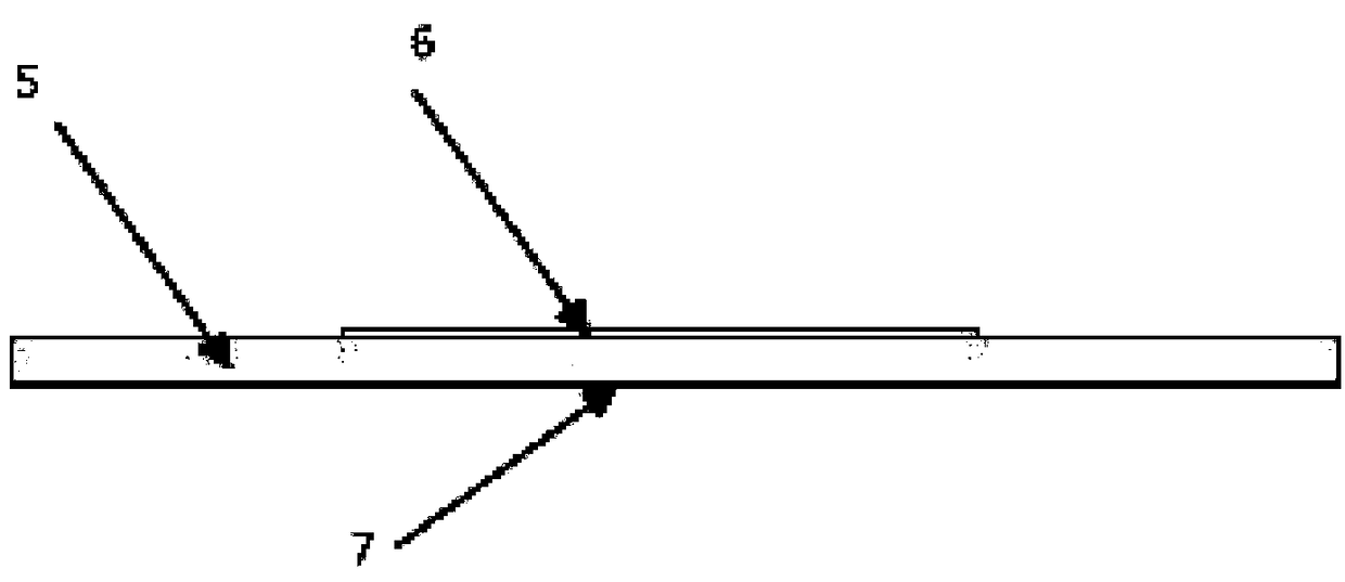
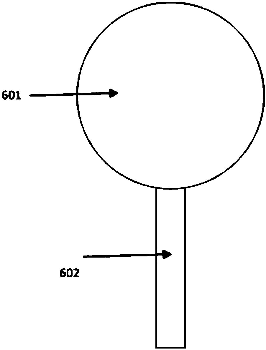
[0032] refer to Figure 1-4 , this embodiment shows a direction reconfigurable antenna:

[0033] Including module A and module B, module A is a medium fluid reflector, which includes a curved base 1, cylindrical hollow thin tubes 201, 202, 203, 204, 205, 205, 207, fluid inlet joint 301, fluid outlet joint 302 , the medium fluid composition 4; module B is a circular monopole microstrip patch antenna, which includes a dielectric substrate 5, an antenna front 6, and a metal floor 7;

[0034] In this embodiment, the arc-shaped base 1 is composed of a rectangular hollow tube with a 120° arc bend. The wall thickness of the rectangular hollow tube is 1 mm, and the pipe size of the rectangular hollow tube is 5×4 mm2. A fluid inlet connector 301 and a fluid outlet connector 302 are respectively installed directly below the end;

[0035] In this embodiment, the arc-shaped base 1 and the cylindrical hollow thin tubes 201, 202, 203, 204, 205, 205, and 207 are all connected internally, s...


PUM


Abstract

The invention relates to a direction reconfigurable antenna. The antenna comprises a module A consisting of a dielectric fluid reflector and a module B consisting of a planar monopole antenna; the module A comprises an arc-shaped base, cylindrical hollow thin tubes, a fluid inlet joint, a fluid outlet joint and a dielectric fluid; the module B is a circular monopole microstrip patch antenna whichmainly comprises a dielectric substrate, an antenna front face and a metal ground; the arc-shaped base is formed by a rectangular hollow tube with an arc-shaped curvature of theta degrees, and the fluid inlet joint and the fluid outlet joint are formed right below the two ends of the arc-shaped base respectively; the arc-shaped base is communicated with the cylindrical hollow thin tubes, so that fluid in the hollow tubes is controlled at the same height.

Description

technical field [0001] The present invention shows a smart antenna for adjusting the direction of the antenna based on fluid, specifically, a direction reconfigurable antenna. Background technique [0002] The direction reconfigurable antenna is a kind of smart antenna, because it can switch the main lobe of the antenna to the target direction, thereby improving the quality of signal transmission, and at the same time playing a certain role in suppressing interference signals. [0003] At present, the commonly used pattern reconfigurable antenna adopts the method of using electronic components to control the switching of the pattern. The disadvantage of this method is that the rated power of the electronic components is limited, and it cannot be applied in high-power occasions, and the electronic components must be Using a bias circuit to provide energy increases energy usage for the overall system. [0004] Therefore, it is necessary to provide a directional reconfigurable...

Claims


Application Information

Patent Timeline
Patent Type & Authority Applications(China)
IPC IPC(8): H01Q1/36H01Q1/48H01Q1/50
CPCH01Q1/36H01Q1/48H01Q1/50
Inventor 袁涛
Owner 袁涛
Learn More