
Power grid adaptability testing device

A technology of adaptability testing and testing equipment, which is applied in the direction of measuring equipment, measuring electricity, measuring electrical variables, etc., can solve the problems of unfavorable fire protection of equipment inside the shell of the testing equipment, vibration of equipment inside the shell of the testing equipment, etc., and achieve the goal of improving insulation performance Effect

Inactive Publication Date: 2018-11-13
董晨晖
View PDF12 Cites 3 Cited by
  • Summary
  • Abstract
  • Description
  • Claims
  • Application Information

AI Technical Summary

Problems solved by technology

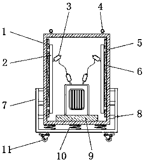
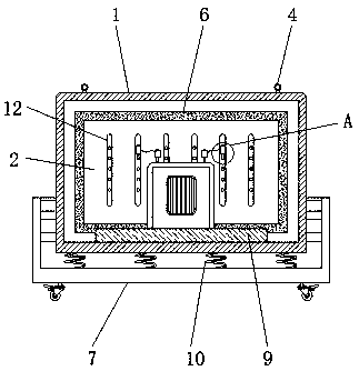
[0003] The purpose of the present invention is to provide a power grid adaptability test device to solve the problem that the existing power grid adaptability test device proposed in the above background technology is likely to cause vibration of the equipment inside the test device shell during transportation, and it is not conducive to Problems with fire protection of equipment inside test fixture enclosures

Method used


Image

  • Power grid adaptability testing device
  • Power grid adaptability testing device
  • Power grid adaptability testing device

Examples


Embodiment Construction

[0020] The following will clearly and completely describe the technical solutions in the embodiments of the present invention with reference to the accompanying drawings in the embodiments of the present invention. Obviously, the described embodiments are only some, not all, embodiments of the present invention. Based on the embodiments of the present invention, all other embodiments obtained by persons of ordinary skill in the art without making creative efforts belong to the protection scope of the present invention.

[0021] In the description of the present invention, it should be noted that the terms "center", "upper", "lower", "left", "right", "vertical", "horizontal", "inner", "outer" etc. indicate The orientation or positional relationship is based on the orientation or positional relationship shown in the drawings, and is only for the convenience of describing the present invention and simplifying the description, rather than indicating or implying that the referred de...


PUM


Abstract

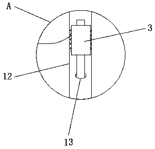
The invention discloses a power grid adaptability testing device which comprises a test device shell, a wiring terminal, a fireproof felt, a rubber column, an insulation base and a movable pulley, wherein the top end of the test device shell is in threaded connection with a lifting ring, and the inner side of the test device shell is connected with an installation plate through an insulation block, the lower end of the wiring terminal is in threaded connection with the installation hole, the installation hole is formed in the installation groove, and the fireproof felt is located between the test device shell and the installation plate, the rubber column is located between the lower portion of the outer side of the shell of the test device and the inner side surface of the damping device,and a damping spring is arranged between the lower end surface of the test device shell and the inner bottom surface of the damping device, the insulation base is arranged below the interior of the test device shell, and the movable pulley is located at the lower end of the damping device. The power grid adaptability testing device is characterized in that the fireproof felt is arranged between the installation plate and the side wall of the test device shell, so that the fireproof protection of the equipment inside the test device shell can be achieved.

Description

technical field [0001] The invention relates to the technical field of power grid testing devices, in particular to a power grid adaptability testing device. Background technique [0002] As the pace of human pursuit of clean energy continues to accelerate, new energy power generation has been developed more extensively, and photovoltaic power stations are also centrally connected to the power system, and their proportion in the power structure of the power system has also increased significantly. For adaptability testing, the traditional transportation will easily cause the vibration of the equipment inside the test device shell, and it is not conducive to the fire protection of the equipment inside the test device shell. Contents of the invention [0003] The purpose of the present invention is to provide a power grid adaptability test device to solve the problem that the existing power grid adaptability test device proposed in the above background technology is likely t...

Claims


Application Information

Patent Timeline
Patent Type & Authority Applications(China)
IPC IPC(8): G01R31/00
CPCG01R31/00
Inventor 董晨晖王俏俏林祺蓉刘淑莉管荑刘勇李莉马洪文刘红霞
Owner 董晨晖
Learn More