


Quick Research
Generate reliable direction feasibility study reports for your R&D in just a few steps.

Technical Q&A
Discover and master advanced knowledge NOW. Basics, ideas, possibilities, all at once.

Find Solutions
As an expert in R&D theories, this can generate solutions to your technical problems instantly.

Evaluate Feasibility
Analyze your overall solution with one click, know your potential R&D risks in advance.

Monitor Landscape
Get weekly tech updates, stay abreast of the latest tech innovations and key insights.
Rotatable creeping sand quantity collector capable of measuring different incoming wind directions
A collector and creeping technology, which is applied in the field of rotatable creeping sand collectors, can solve the problems of inability to complete observation tests, and achieve the effect of ensuring accuracy and precision.
- Summary
- Abstract
- Description
- Claims
- Application Information
AI Technical Summary
Problems solved by technology
Method used
Image


Examples
Embodiment 1
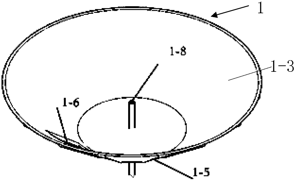
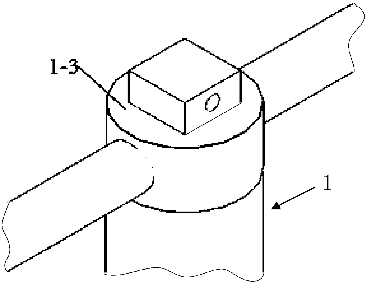
[0051]An embodiment of the present invention provides a rotatable creeping sand collector for measuring different wind directions, which includes: a wind vane 1-1, a wind vane vertical rod 1-2, a first conical base 1-3, and a rotating shaft 2 -4 and the base sand collector 3, the top of the first conical base 1-3 is a plane 1-7, and the side wall of the first conical base 1-3 is provided with a sand guiding arc surface 1- 4. The bottom end of the wind vane vertical rod 1-2 is connected to the top end of the first conical base 1-3, and the top end of the wind vane vertical rod 1-2 is connected to the middle part of the wind vane 1-1, so The sand guide arc surface 1-4 is provided with a plurality of sand guide partitions 1-5 protruding from the sand guide arc surface 1-4, and the sand guide arc surface 1-4 is provided with a sand inlet 1-6 , the two sides of the sand inlet 1-6 are respectively provided with the sand guiding partitions 1-5; the bottom end of the first conical bas...
Embodiment 2
[0070] On the basis of Embodiment 1, the base sand collector 3 of this embodiment also includes: a baffle 3-2, the baffle 3-2 is an annular structure, and the baffle 3-2 is connected to The base sand collector 3 is arranged concentrically, and the baffle 3-2 is arranged between the effective sand collection box 3-4 and the invalid sand collection box 3-5; the effective sand collection box 3-4 and the number of orientation sandboxes of the invalid sandbox 3-5 are 16, and the orientation sandbox of the effective sandbox 3-4 is the same as that of the invalid sandbox 3-5. Azimuth set sandboxes have a one-to-one correspondence in the radial direction.
[0071] The setting of the baffle makes the base sand collector be divided into the azimuth sand collection box of the effective sand collection box and the invalid sand collection box, so that the amount of creeping sand in the direction of the wind will be accurately separated from the amount of creeping sand in other similar dire...
Embodiment 3
[0073] On the basis of Embodiment 1, the center line of the sand inlet 1-6 in this embodiment is in the same direction as the tail of the wind vane 1-1.
[0074] The center line of the sand inlet is in the same direction as the tail of the wind vane. Under the action of the wind force, the tail of the wind vane is facing the direction of the incoming wind, so that the sand inlet can always face the direction of the incoming wind, which is convenient for creeping sand in the direction of the incoming wind. The particles enter the sand inlet, so that the sand particles collected in the effective sand collection box are all creeping sand particles blown from the direction of the wind.
PUM
| Property | Measurement | Unit |
|---|---|---|
| Radial width | aaaaa | aaaaa |
Abstract
Description
Claims
Application Information
 - R&D Engineer
- R&D Manager
- IP Professional
- Industry Leading Data Capabilities
- Powerful AI technology
- Patent DNA Extraction
Browse by: Latest US Patents, China's latest patents, Technical Efficacy Thesaurus, Application Domain, Technology Topic, Popular Technical Reports.
© 2024 PatSnap. All rights reserved.Legal|Privacy policy|Modern Slavery Act Transparency Statement|Sitemap|About US| Contact US: help@patsnap.com