
Family type clean energy station

An energy station, clean technology, applied in the direction of heat exchanger type, heat storage heater, fluid heater, etc., can solve the problems of inability to start, low efficiency of air heat source pump, high cost, and achieve uniform heat storage and heat release, A wide range of heating temperature zones and the effect of reducing the cost of use

Pending Publication Date: 2018-11-13
SHANDONG HUACHUN NEW ENERGY
View PDF7 Cites 9 Cited by
  • Summary
  • Abstract
  • Description
  • Claims
  • Application Information

AI Technical Summary

Problems solved by technology

[0003] At present, air source heat pump heating is one of the main methods of coal-to-electricity conversion. Energy saving and environmental protection are favored by everyone, but there are still some problems that limit its application, mainly due to frosting of heat exchangers at low temperatures and low ambient temperatures. poor performance of the
Especially in northern regions, the outdoor temperature in winter can reach minus 10 degrees or even minus 20 degrees. In this environment, the efficiency of the air heat source pump is extremely low, and it may even fail to start, and the heating effect is also very poor. Ideal, unable to meet people's needs
[0004] If a simple electric heater is used for heating, not only the cost is high, but also the heating effect is not ideal

Method used


Image

  • Family type clean energy station
  • Family type clean energy station
  • Family type clean energy station

Examples


Embodiment 1

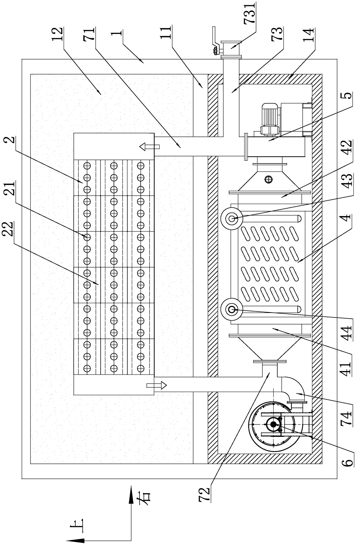
[0035] Such as figure 1 As shown, a household type clean energy station includes a box body 1, a partition 11 is arranged in the middle of the box body 1, and the partition board 11 divides the inner space of the box body 1 into upper and lower parts. For the convenience of description, the upper half is now defined as the heat storage area, and the lower half is defined as the heat release drive area.

[0036] As a specific implementation, the box body 1 described in this embodiment is composed of a square frame and a plate arranged outside the frame, and the frame is welded by section steel.

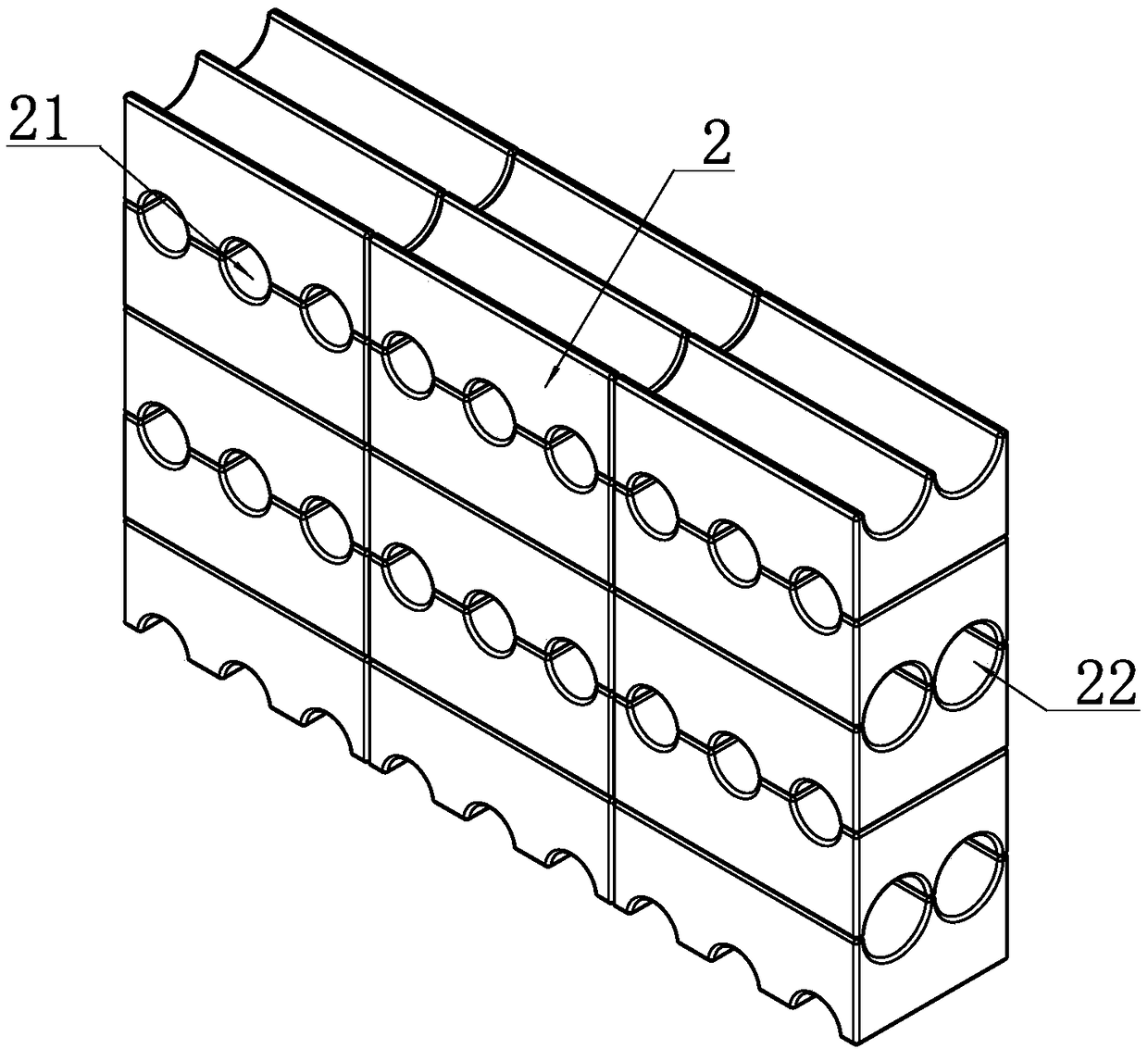
[0037] Such as figure 1 As shown, the heat storage area is provided with a heat storage body 2, and the heat storage body 2 is provided with a plurality of heat storage channels 21 and heat release channels 22, and the heat storage channel 21 is provided with electric heat components. A first thermal insulation layer 12 is arranged between the heat storage body 2 and the box body 1 ...

Embodiment 2

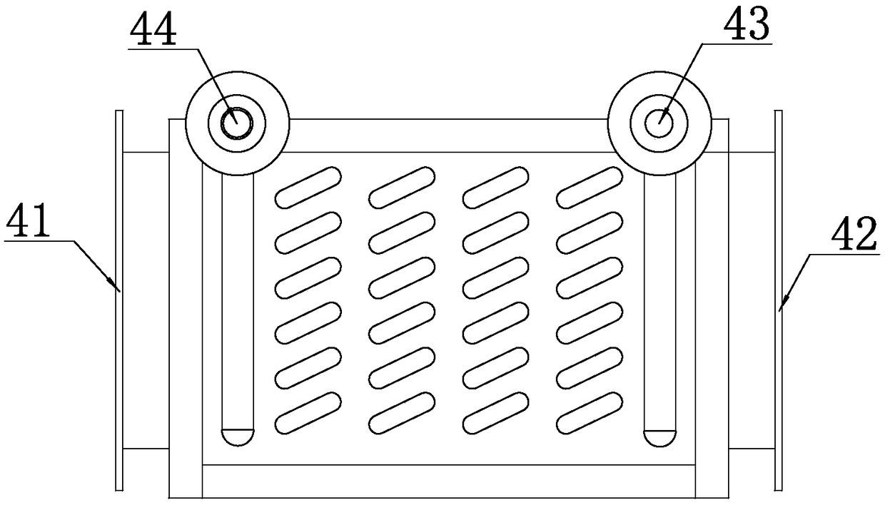
[0053] The inner surface of the heat release groove is provided with uneven texture, and the rest of the structure is the same as the first embodiment.

[0054] In this way, the disturbance of the wind in the pipeline during the heat release process can be increased, the heat exchange can be enhanced, and the heat exchange efficiency can be improved.


PUM


Abstract

The invention discloses a family type clean energy station. The energy station comprises a box and a partition plate. The partition plate divides the internal space of the box into a heat storage areaand a heat release drive area. A heat storage body is arranged in the heat storage area and internally provided with heat storage channels and heat release channels. Electric heating assemblies are arranged in the heat storage channels correspondingly. A first heat preservation layer is arranged between the heat storage body and the box. A heat exchanger and a first fan are arranged in the heat release drive area. A shell side outlet of the heat exchanger communicates with an inlet of the first fan. An outlet of the first fan communicates with one ends of the heat release channels through a first pipeline. The other ends of the heat release channels communicate with a shell side inlet of the heat exchanger through a second pipeline. According to the energy station, the national off-peak electricity policy of power peak shaving and valley filling is fully utilized, the energy station is not influenced by the external environment temperature, and the heating requirements of the family type clean energy station for heating, domestic hot water, domestic drying, baking, blanching and the like can be met.

Description

technical field [0001] The invention relates to the technical field of heating and heating, in particular to a family-type clean energy station suitable for rural areas. Background technique [0002] In recent years, calls for "coal-to-electricity" and "coal-to-gas" under the call for clean heating have become increasingly louder, and many provinces in the north have put forward implementation opinions on promoting coal-to-electricity for heating in rural areas, aiming to comprehensively improve rural heating pollution control level, adjust and optimize the rural heating energy structure, and promote the use of green and clean energy. [0003] At present, air source heat pump heating is one of the main methods of coal-to-electricity conversion. Energy saving and environmental protection are favored by everyone, but there are still some problems that limit its application, mainly due to frosting of heat exchangers at low temperatures and low ambient temperatures. problems su...

Claims


Application Information

Patent Timeline
Patent Type & Authority Applications(China)
IPC IPC(8): F24H7/04F24H9/18F24H9/20F28D20/00F28F27/00
CPCF24H7/0416F24H9/1809F24H9/2028F28D20/0056F28F27/00F28D2020/0065Y02E60/14
Inventor 江红阳朱卫星张凤娟江宾郭志东
Owner SHANDONG HUACHUN NEW ENERGY
Learn More