
A lamp assembly for use in a headlamp

A lamp assembly and headlamp technology, which can be applied to parts of lighting devices, semiconductor devices of light-emitting elements, headlights, etc., and can solve problems such as misalignment and poor registration.

Active Publication Date: 2018-11-13
VALEO NORTH AMERICA
View PDF7 Cites 1 Cited by
  • Summary
  • Abstract
  • Description
  • Claims
  • Application Information

AI Technical Summary

Problems solved by technology

Installing light pipes into heat sinks is often blind and can easily lead to misalignment or misregistration of the light pipe entrance face relative to the LEDs

Method used


Image

  • A lamp assembly for use in a headlamp
  • A lamp assembly for use in a headlamp
  • A lamp assembly for use in a headlamp

Examples


Embodiment Construction

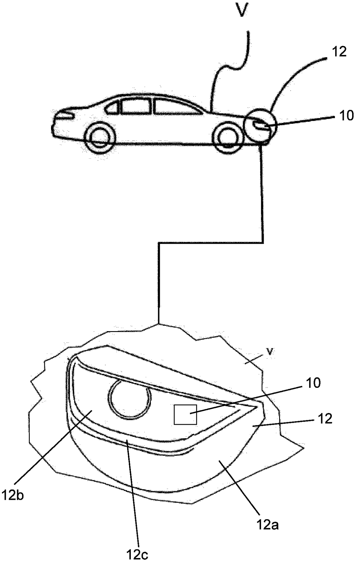
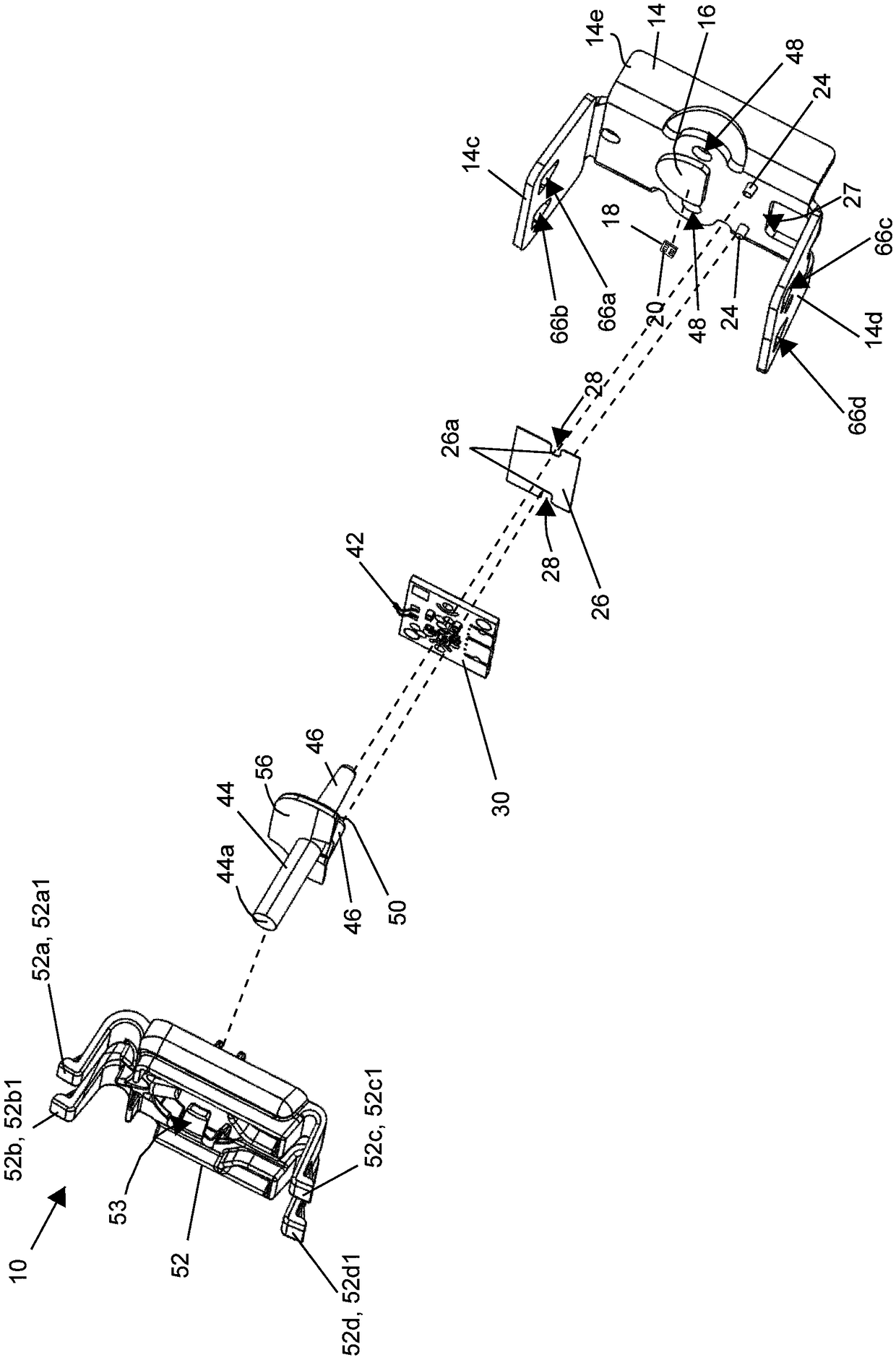
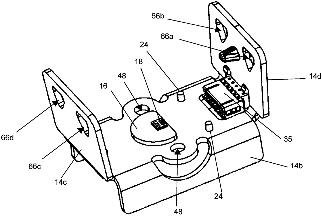
[0048] now refer to figure 1 , the lamp assembly 10 is shown installed in a headlamp assembly 12 of a vehicle V. As shown in FIG. The headlamp assembly 12 includes a frame or housing 12a , a lens 12b and a seal 12c that generally seals the lamp assembly 10 in the headlamp assembly 12 . Lamp assembly 10 includes a heat sink 14 stamped from a single sheet of material (not shown) and configured as figure 2 shown in the exploded diagram. The heat sink 14 is an integral unitary or monolithic structure, and is machined or folded to include a first wall 14a, a second wall 14b generally opposite the first wall 14a ( image 3 ), a first end wall 14c and a second end wall 14d generally opposite to the first end wall 14c, such as figure 2shown. Note that the heat sink 14 includes a crescent or half-moon shaped landing pad or area 16 adapted to receive a light source 18 which may include at least one or more light emitting diodes (LEDs) 20 . In the figure, at least one LED 20 is mo...


PUM


Abstract

A lamp assembly for mounting in a headlamp comprising a heat sink having a printed circuit board landing area for receiving a printed circuit board and a light source landing area for receiving at least one light source. The lamp assembly also comprises a light guide and a bracket for detachably mounting on the heat sink. The bracket is adapted to engage and secure the light guide in a predetermined position on the heat sink, the at least one light source and the printed circuit board a unsealed in the heat sink.

Description

technical field [0001] The present invention relates to motor vehicle headlamps, and more particularly, to a lamp assembly within a headlamp. Background technique [0002] In the field of motor vehicle lighting, LEDs may be used in combination with light pipes to provide motor vehicle lighting functions. In the past, LEDs were mounted directly to a printed circuit board (PCB), which in turn was mounted to a heat sink, requiring a heat sink to dissipate the heat generated by the PCB and the LEDs mounted on the PCB. The light pipe is typically positioned such that its input face is in operative relationship with the LED. [0003] The radiator is then mounted on the outside of the headlamp and mounted on the housing on the motor vehicle. This requires sealing or sealing the heat sink to the housing. Therefore, a seal must be provided to seal the heat sink and components mounted on the heat sink, including printed circuit boards and LEDs. Since the LEDs are mounted directly ...

Claims


Application Information

Patent Timeline
Patent Type & Authority Applications(China)
IPC IPC(8): F21S41/00F21S45/47F21V23/00F21V31/00F21W107/10F21Y115/10
CPCF21S41/00F21S45/47F21V23/003F21V31/005F21Y2115/10F21W2107/10F21S43/195F21S43/14F21S43/27F21S43/237F21S43/243F21S43/247H05K1/0203B60Q1/04H05K2201/10106B60Q2400/30F21S41/24F21S41/192F21S41/141
Inventor 加文·弗朗西斯·华纳朱利安·埃蒙弗雷德里克·艾伦·罗斯乔纳森·迈克尔·布兰丁基思·爱德华·切瑟
Owner VALEO NORTH AMERICA
Learn More