
Electrical automation equipment balance base

A technology of electrical automation and equipment, which is applied in the direction of mechanical equipment, supporting machines, machine tables/supports, etc., can solve the problems that the base cannot adjust the balance of equipment, inconvenient movement, and the impact of machine balance, so as to avoid excessive vibration frequency Effect

Inactive Publication Date: 2018-11-13
赵瑞霞
View PDF4 Cites 0 Cited by
  • Summary
  • Abstract
  • Description
  • Claims
  • Application Information

AI Technical Summary

Problems solved by technology

[0002] At present, the existing electrical automation equipment is large in size and inconvenient to move, especially when placing electrical automation equipment, it will be affected by whether the placement surface is balanced, which will affect the overall balance of the machine and cause the machine to generate large The vibration of the machine reduces the service life of the machine. The bottom of the electrical automation equipment is generally equipped with a base, but the base cannot be adjusted and the balance of the equipment is maintained. In order to solve the above problems

Method used


Image

  • Electrical automation equipment balance base
  • Electrical automation equipment balance base
  • Electrical automation equipment balance base

Examples


Embodiment Construction

[0021] In order to make the technical means, creative features, goals and effects achieved by the present invention easy to understand, the present invention will be further described below in conjunction with specific embodiments.

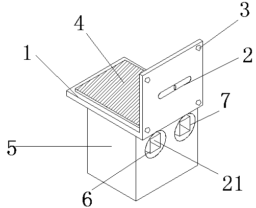
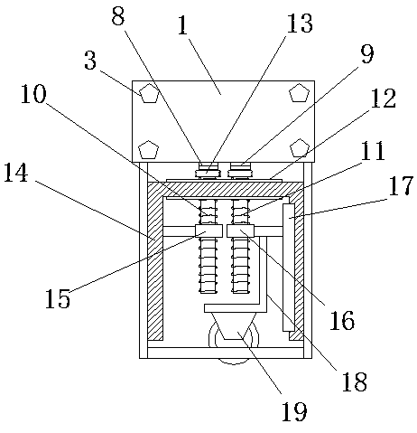
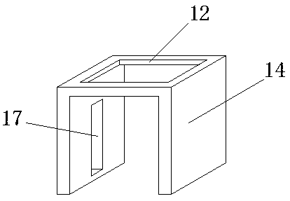
[0022] Such as Figure 1-6 As shown, a balance base of electrical automation equipment includes a foot plate 1, an outer shell 5 and a level pipe 2, the bottom end of the foot plate 1 is fixed with the outer shell 5, and the middle part of the side wall of the foot plate 1 is equipped with a level pipe 2, The inner wall of the outer casing 5 is equipped with a lifting stand 14, and the top inside the outer casing 5 is equipped with a first rotating shaft 8, a second rotating shaft 9 and a fixed shaft plate 20, and the first rotating shaft 8 and the second rotating shaft 9 Located on the back side of the fixed shaft plate 20, the bottoms of the first rotating shaft 8 and the second rotating shaft 9 are respectively fixed with a first screw mandrel ...


PUM


Abstract

The invention discloses an electrical automation equipment balance base. The electrical automation equipment balance base comprises a foot plate, an outer housing and a level tube; the outer housing is fixedly arranged at the bottom end of the foot plate; the level tube is arranged in the middle of the side wall of the foot plate; a lifting foot stand is mounted at the inner wall of the outer housing; a first rotary shaft, a second rotary shaft and a shaft fixing plate are mounted at the top end in the outer housing; the first rotary shaft and the second rotary shaft are located on the back side of the shaft fixing plate; a first lead screw is fixedly arranged at the bottom of the first rotary shaft; a second lead screw is fixedly arranged at the bottom of the second rotary shaft; driven teeth are mounted at the top ends of the first lead screw and the second lead screw; the first lead screw is connected with a first nut housing; and the second lead screw is connected with a second nuthousing. The level tube is mounted at the side wall of the foot plate, and when equipment is mounted through the base, whether the four corners of the equipment are mounted on a unified horizontal plane can be known exactly, so that follow-up adjustment is facilitated; a machine is prevented from being integrally affected by unbalance; and the electrical automation equipment balance base is relatively practical and suitable for extensive popularization and use.

Description

technical field [0001] The invention relates to a balance base, in particular to an electrical automation equipment balance base. Background technique [0002] At present, the existing electrical automation equipment is large in size and inconvenient to move, especially when placing electrical automation equipment, it will be affected by whether the placement surface is balanced, which will affect the overall balance of the machine and cause the machine to generate large The vibration reduces the service life of the machine. The bottom of the electrical automation equipment is generally equipped with a base, but the base cannot be adjusted and the balance of the equipment can be maintained. In order to solve the above-mentioned problems. Therefore, we propose a balance base for electrical automation equipment. Contents of the invention [0003] The main purpose of the present invention is to provide a balance base for electrical automation equipment. A level pipe is insta...

Claims


Application Information

Patent Timeline
Patent Type & Authority Applications(China)
IPC IPC(8): F16M11/24F16M11/04
Inventor 赵浩
Owner 赵瑞霞
Learn More