


Quick Research
Generate reliable direction feasibility study reports for your R&D in just a few steps.

Technical Q&A
Discover and master advanced knowledge NOW. Basics, ideas, possibilities, all at once.

Find Solutions
As an expert in R&D theories, this can generate solutions to your technical problems instantly.

Evaluate Feasibility
Analyze your overall solution with one click, know your potential R&D risks in advance.

Monitor Landscape
Get weekly tech updates, stay abreast of the latest tech innovations and key insights.
Remote-control electric outboard motor propeller
A technology of propellers and electric boats, applied in the field of remote control boats, can solve the problems of high vibration intensity, low stability, and difficulty in operation, and achieve the effects of increasing the installation force area, the connection strength, and the stability.
- Summary
- Abstract
- Description
- Claims
- Application Information
AI Technical Summary
Problems solved by technology
Method used
Image


Examples
Embodiment 1
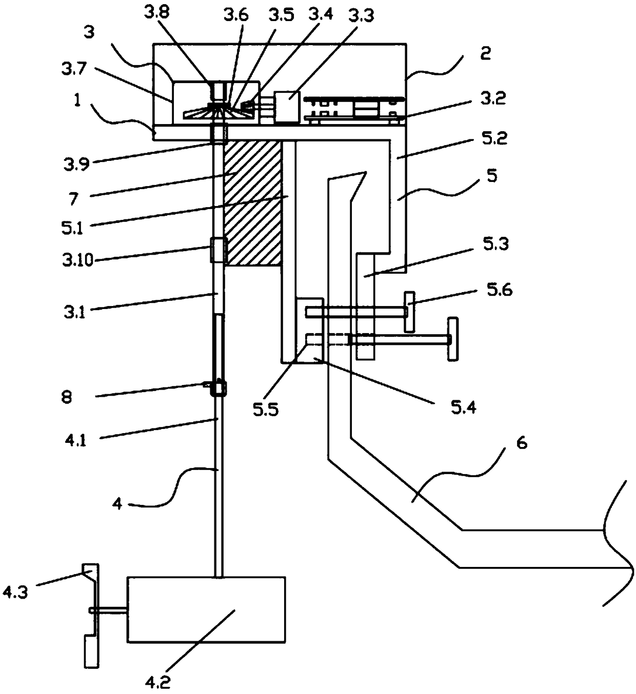
[0027] A remote control electric outboard motor propeller, comprising a base 1, a casing 2, a direction assembly 3, a propulsion assembly 4, and a clamping assembly 5, the upper part of the base 1 is provided with a hollow shell 2, and the lower part of the base 1 is provided with There is a clamping assembly 5, the direction assembly 3 is located on the upper part of the base 1 away from the end of the clamping assembly 5 and the direction assembly 3 is located inside the housing 1, and the direction shaft 3.1 in the direction assembly 3 protrudes downward from the base 1 and is movably connected with the propulsion assembly 4, and a reinforcing plate 7 is connected between the direction shaft 3.1 and the clamping assembly 5.
[0028] As a preferred implementation of this embodiment, the direction assembly 3 includes an integrated controller 3.2, a direction motor 3.3, a direction machine gear 1 3.4, a direction machine gear 2 3.5, a direction sensor 3.6, and a direction shaft...
Embodiment 2
[0037] The difference between the present embodiment and the first embodiment is that, as a preferred embodiment of the present embodiment, the steering gear 2 3.5 is arranged on the part of the steering shaft 3.1 protruding from the top of the steering assembly fixing bracket 3.7, so Said direction motor 3.3 is arranged on the inner side of direction component fixed bracket 3.7, and said direction machine gear one 3.4 and direction machine gear two 3.5 are flat gears. In specific use, different structures can be used according to different powers. Bevel gears are suitable for low-power situations, and spur gears are suitable for high-power situations.
[0038] Among them, the central control circuit 3.2a selects the STC89C52 single-chip microcomputer as the controller, and the single-chip timer module outputs the PWM signal and controls the direction motor 3.3 and the propulsion motor 4.2 through the direction motor control circuit 3.2b and the propulsion motor control circuit...
PUM
 Abstract
Description
Claims
Application Information
 - R&D Engineer
- R&D Manager
- IP Professional
- Industry Leading Data Capabilities
- Powerful AI technology
- Patent DNA Extraction
Browse by: Latest US Patents, China's latest patents, Technical Efficacy Thesaurus, Application Domain, Technology Topic, Popular Technical Reports.
© 2024 PatSnap. All rights reserved.Legal|Privacy policy|Modern Slavery Act Transparency Statement|Sitemap|About US| Contact US: help@patsnap.com