Jig processing method, jig and lathe

A processing method and fixture technology, applied in the direction of metal processing equipment, metal processing machinery parts, manufacturing tools, etc., can solve the problems of inability to ensure accurate punching distance, reduced processing efficiency, and reduced product yield, so as to improve processing Accuracy and processing efficiency, improve product yield, reduce the effect of machine adjustment difficulty

Active Publication Date: 2020-01-14
GEER TECH CO LTD
View PDF7 Cites 0 Cited by
  • Summary
  • Abstract
  • Description
  • Claims
  • Application Information

AI Technical Summary

Problems solved by technology

However, due to certain errors in the assembly process, the distance between the punched holes of the assembled two connecting plates cannot be accurately guaranteed
As a result, there will be processing errors during the fine processing of the parts to be processed, which will cause a decrease in product yield and processing efficiency

Method used


Image

  • Jig processing method, jig and lathe
  • Jig processing method, jig and lathe
  • Jig processing method, jig and lathe

Examples


Embodiment Construction

[0029] The following will clearly and completely describe the technical solutions in the embodiments of the present invention with reference to the accompanying drawings in the embodiments of the present invention. Obviously, the described embodiments are only part of the embodiments of the present invention, not all of them. Based on the embodiments of the present invention, all other embodiments obtained by persons of ordinary skill in the art without creative efforts fall within the protection scope of the present invention.

[0030] It should be noted that all directional indications (such as up, down, left, right, front, back...) in the embodiments of the present invention are only used to explain the relationship between the components in a certain posture (as shown in the accompanying drawings). Relative positional relationship, movement conditions, etc., if the specific posture changes, the directional indication will also change accordingly.

[0031] In the present in...


PUM

PropertyMeasurementUnit
surface roughnessaaaaaaaaaa

Abstract

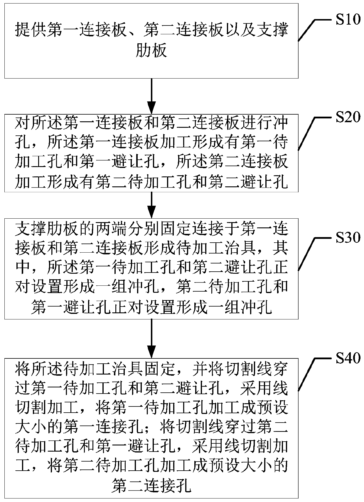
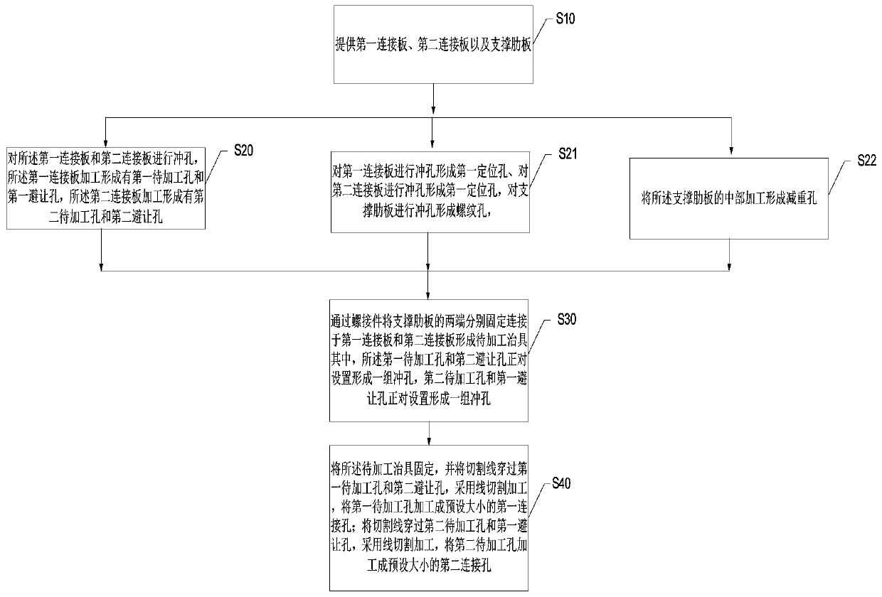
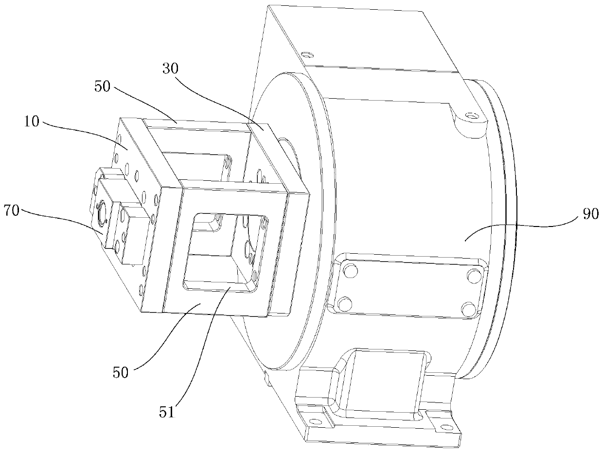
The invention discloses a jig machining method, a jig and a turning lathe. The jig machining method comprises the steps that a first connecting plate, a second connecting plate and a supporting ribbedplate are provided; the first connecting plate and the second connecting plate are punched, so that a first to-be-machined hole and a first receding hole are machined in the first connecting plate, and a second to-be-machined hole and a second receding hole are machined in the second connecting plate; the two ends of the supporting ribbed plate are fixedly connected to the first connecting plateand the second connecting plate separately to form a to-be-machined jig; the to-be-machined jig is fixed, a cutting wire penetrates through the first to-be-machined hole and the second receding hole,and the first to-be-machined hole is machined into a first connecting hole with a preset size through wire cutting; and the cutting wire penetrates through the second to-be-machined hole and the firstreceding hole, and the second to-be-machined hole is machined into a second connecting hole with a preset size through wire machining. By adoption of the technical scheme, the machining precision andthe machining efficiency can be improved, the adjustment difficulty is lowered, and the product yield is increased.

Description

technical field [0001] The invention relates to the technical field of workpiece processing, in particular to a processing method of a jig, a jig processed by the processing method, and a lathe using the jig. Background technique [0002] In the field of metal product processing, it is necessary to use jigs to fix the parts on the lathe for processing. For example, when CNC four-axis is processing some special structures, such as the side button hole of the watch case, it is necessary to use a jig to fix the part to be processed to the end face four-axis tailstock. At this time, the workpiece to be processed needs to be installed on one surface of the jig, and then the other surface of the jig is installed on the end face four-axis tailstock, and then the end face four-axis tailstock is installed on the machine tool to complete the processing of the parts to be processed. Prepare. [0003] Existing jigs generally need to be separated into two connecting plates and supporti...

Claims


Application Information

Patent Timeline
Patent Type & Authority Patents(China)
IPC IPC(8): B23P15/00B23Q3/06
CPCB23P15/00B23Q3/06
Inventor 马洪龙高统帅唐思敏
Owner GEER TECH CO LTD
Why Eureka
Try Eureka