
A welding method for realizing T-joint between ultra-thin plate and small-diameter bar

A welding method and small-diameter technology, applied in welding equipment, resistance welding equipment, metal processing equipment, etc., can solve the problems of large resistance difference, difficulty in repeatedly obtaining joints, offset, etc., and achieve the effect of avoiding overheating damage

Active Publication Date: 2019-11-29
NANCHANG HANGKONG UNIVERSITY
View PDF6 Cites 0 Cited by
  • Summary
  • Abstract
  • Description
  • Claims
  • Application Information

AI Technical Summary

Problems solved by technology

[0003] The problem to be solved by the present invention is that it is difficult to clamp such T-shaped joints by conventional resistance welding, and there are defects such as poor nugget and offset due to the large resistance difference between the two materials, and small-diameter bars are easily damaged by overheating due to excessive heating. At the same time, the lengths of small-diameter bars are not exactly the same when welding actual products, and the resistance of small-diameter bars due to different lengths makes it difficult to repeatedly obtain joints with the same welding quality under the same welding parameters

Method used


Image

  • A welding method for realizing T-joint between ultra-thin plate and small-diameter bar
  • A welding method for realizing T-joint between ultra-thin plate and small-diameter bar
  • A welding method for realizing T-joint between ultra-thin plate and small-diameter bar

Examples


Embodiment 1

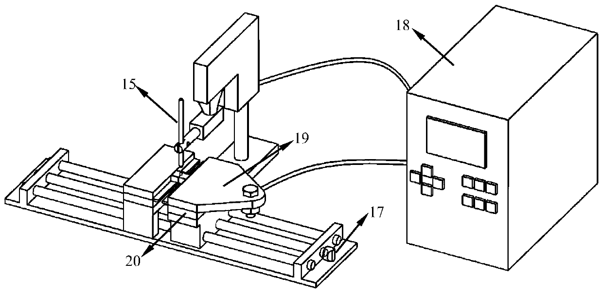
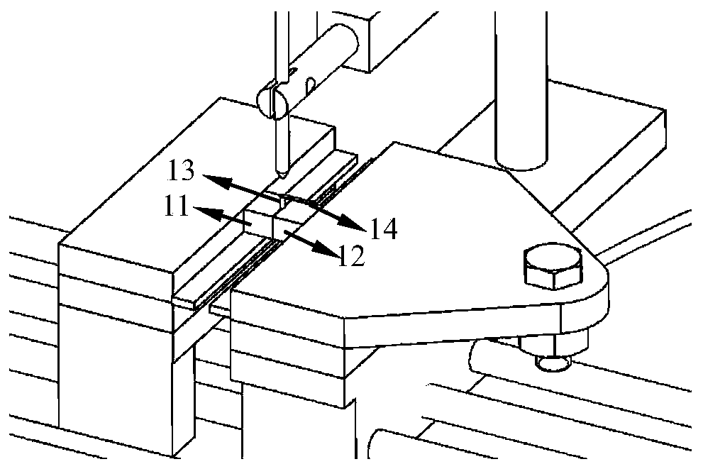
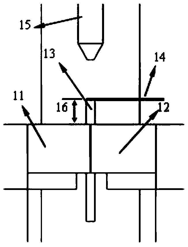
[0028] The invention relates to a welding method for realizing a T-shaped connection between an ultra-thin plate and a small-diameter bar, figure 1 It is a welding device of the present invention and an assembly schematic diagram, figure 2 for figure 1 Zoom in on part of the schematic, image 3 Schematic diagram for welding. The material of the small-diameter bar is pure molybdenum with a diameter of 1.2mm, and the material of the ultra-thin metal plate is 304 stainless steel with a thickness of 0.3mm. First, use 800-grit sandpaper to polish the end surface of the molybdenum rod to be welded evenly, and polish the stainless steel ultra-thin plate to be welded to remove the surface oxide layer. The molybdenum rods and stainless steel ultra-thin plates were cleaned in an ultrasonic cleaning pool with acetone, and dried after cleaning. Loosen the tightening knob (17), place the small-diameter rod (13) between the movable conductive block one (11) and the movable conductive b...


PUM

PropertyMeasurementUnit
diameteraaaaaaaaaa
thicknessaaaaaaaaaa
thicknessaaaaaaaaaa

Abstract

The invention relates to a welding method for realizing a T-shaped connection between an ultra-thin plate and a small-diameter bar. In a miniature resistance welding device, a movable conductive block one (11) and a movable conductive block two (12) are placed between a A small-diameter bar (13) to be welded is a processing method for welding homogeneous or dissimilar metal materials including a small-diameter bar and a layer of ultra-thin plates (14). The welding device involved in the present invention can use the small-diameter bar as the lower electrode of micro-resistance spot welding. When welding, the ultra-thin plate is placed on the upper end of the small-diameter bar. After the upper electrode (15) is pressed and energized, the ultra-thin plate and the The small diameter rods of the electrodes are joined together. The invention solves the problem that conventional resistance welding is usually suitable for lap welding between two plates, such T-shaped joints are difficult to clamp, poor nugget and offset due to large resistance differences of materials, and small-diameter bars are easy to weld. Overheating damage and other problems, the welded joints have high strength, and the welding steps are simple.

Description

technical field [0001] The invention relates to a welding method for realizing a T-shaped connection between an ultra-thin plate and a small-diameter bar, and belongs to the field of welding technology. Background technique [0002] Resistance welding is to press the workpiece to be welded between two electrodes, and after applying current, use the resistance heating effect generated by the current flowing through the contact surface of the workpiece and the adjacent area to heat it to a molten or plastic state to form a metal bond. method. Among them, the resistance of an important factor in the resistance thermal effect is determined by the resistance of the material to be welded (ie, the bulk resistance) and the resistance of the contact surface of the two materials to be welded. The workpiece to be welded by conventional resistance welding must be placed between the upper and lower electrodes. It is generally suitable for the lap connection between two plates. 0.8mm~2m...

Claims


Application Information

Patent Timeline
Patent Type & Authority Patents(China)
IPC IPC(8): B23K11/11B23K11/00B23K11/36
CPCB23K11/00B23K11/11B23K11/115B23K11/36
Inventor 陈玉华李树寒刘颖冯良清黄永德曹文明
Owner NANCHANG HANGKONG UNIVERSITY
Learn More