Welding aids

A technology of auxiliary equipment and welding tongs, which is applied in welding equipment, manufacturing tools, resistance welding equipment, etc., can solve the problems of increased welding cost, narrow welding operation space, and low welding efficiency, and achieves convenient welding, large welding operation space, The effect of ensuring welding quality

Active Publication Date: 2021-03-02
CHERY AUTOMOBILE CO LTD
View PDF7 Cites 0 Cited by
  • Summary
  • Abstract
  • Description
  • Claims
  • Application Information

AI Technical Summary

Problems solved by technology

[0002] During the welding process of the car body, the welding of the general position can be completed by electric welding machine, but for some areas with complex spatial structure, such as figure 1 The sunroof 1 on the roof 6 shown in the car, because the opening of the sunroof 1 affects the structural strength of the roof 6, after the window edge of the sunroof 1 is folded down to form the flange 4, it needs to be additionally welded at the edge of the sunroof Reinforcement plate 5 is generally welded on the window flange 4 close to the front of the vehicle in the vehicle length direction and the two window flanges 4 in the vehicle width direction. The window flange 4 in the vehicle length direction and the reinforcement plate arranged vertically 5. The panel surface is overlapped along the vehicle length direction, and the window flange in the vehicle width direction 4 is overlapped with the vertically arranged reinforcing plate panel surface in the vehicle width direction. Due to the narrow welding operation space at the window, and the The overlapping directions of the two plates to be welded are different, and special-shaped welding tongs are required for welding. The installation of special-shaped welding tongs greatly increases the welding cost. In addition, workers need to operate the special-shaped welding tongs to change positions on the outer periphery of the top cover to the length and width of the vehicle. The window flanging on the top is welded separately, which not only increases the labor intensity of the workers, but also reduces the welding efficiency, and manual welding will cause the welding position of the two welded parts to shift, which will affect the welding quality of the window flanging and the reinforcing plate

Method used


Image

  • Welding aids
  • Welding aids
  • Welding aids

Examples


Embodiment Construction

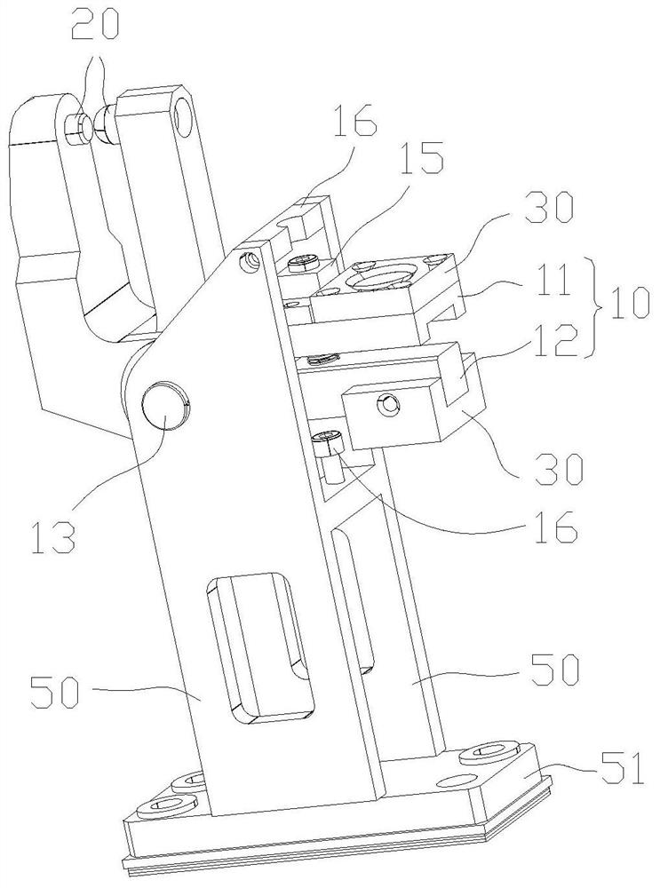
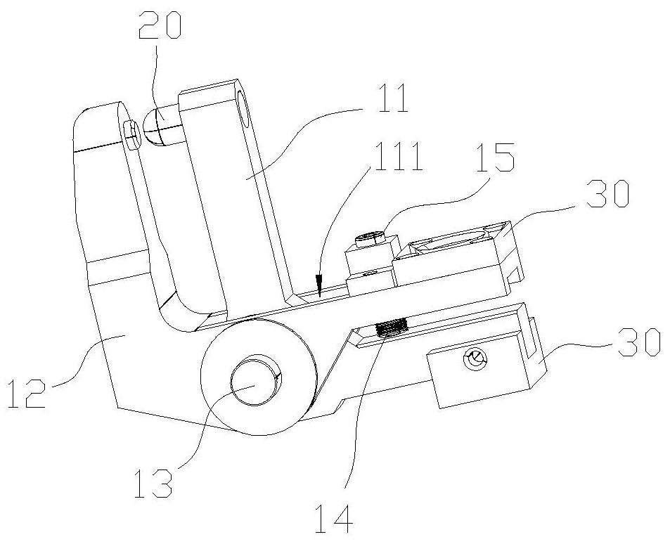
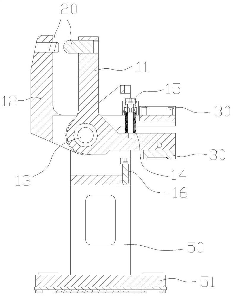
[0013] A welding aid, the top cover 6 to be welded is placed flat on the workbench, one end of the welding tongs arm 10 is arranged with an electrode cap 20, and the other end is connected to an electrode plate 30, and the electrode caps at one end of the two welding tongs arms 10 are 20 points apart. It is placed on both sides of the two plates to be welded and opened and closed in the horizontal direction. The electrode plate 30 at the other end of the two welding tongs arms 10 is located in the window of the skylight 1, and the middle parts of the two welding tongs arms 10 are hinged on the bracket plate 50. The welding tongs 2 open and close in the vertical direction to drive the two electrode plates 30 and drive the electrode caps 20 to approach each other and horizontally clamp the parts to be welded on the two plates.

[0014] In the above scheme, the ordinary welding tongs 2 perform open and close welding actions in the vertical direction, while the window flange 4 in t...


PUM


Abstract

The invention discloses a welding auxiliary tool. A top cover to be welded is placed flat on a workbench, an electrode cap is arranged at one end of a welding tong arm, and an electrode plate is connected at the other end. The two sides of the two plates to be welded are opened and closed in the horizontal direction. The electrode plates at the other ends of the two welding tong arms are located in the skylight window. The middle of the two welding tong arms is hinged on the bracket plate. The opening and closing action drives the two electrode plates and drives the electrode caps to approach each other and horizontally clamp the parts to be welded on the two plates. Avoid manual welding causing the welding position of the two welding parts to shift, and ensure the welding quality of the two welding parts. The electrode plate at the other end of the two welding gun arms is located in the skylight window. Two electrode plates can be used, which greatly facilitates the welding of the flanging of the skylight and the reinforcing plate.

Description

technical field [0001] The invention relates to the field of welding of body parts, in particular to a welding auxiliary tool. Background technique [0002] In the welding process of the car body, the welding of general positions can be completed by electric welding machine, but for some areas with complex spatial structure, such as figure 1 The sunroof 1 on the roof 6 shown in the car, because the opening of the sunroof 1 affects the structural strength of the roof 6, after the window edge of the sunroof 1 is folded down to form the flange 4, it needs to be additionally welded at the edge of the sunroof Reinforcement plate 5 is generally welded on the window flange 4 close to the front of the vehicle in the vehicle length direction and the two window flanges 4 in the vehicle width direction. The window flange 4 in the vehicle length direction and the reinforcement plate arranged vertically 5. The panel surface is overlapped along the vehicle length direction, and the windo...

Claims


Application Information

Patent Timeline
Patent Type & Authority Patents(China)
IPC IPC(8): B23K11/11B23K11/36B23K11/31B23K11/30
CPCB23K11/11B23K11/115B23K11/30B23K11/31B23K11/36
Inventor 余子进高梅李文萍祝桂荣李金梅
Owner CHERY AUTOMOBILE CO LTD
Why Eureka
Try Eureka