Automatic clamping and positioning rolled steel casting mold

An automatic clamping, steel technology, applied in the direction of casting molds, casting mold components, manufacturing tools, etc., can solve problems such as functional limitations of profiles, defective castings, single mold function, etc., to achieve excellent texture, simple structure, easy to dismantle the mold. Effect

Inactive Publication Date: 2018-11-13
应城市砺安智能科技有限公司
View PDF0 Cites 1 Cited by
  • Summary
  • Abstract
  • Description
  • Claims
  • Application Information

AI Technical Summary

Problems solved by technology

[0005] Aiming at the deficiencies of the prior art, the present invention provides a steel casting mold with automatic clamping and positioning, which has the advantages of convenient and time-saving mold removal, and the movable mold core setting enables the mold to be used for casting of different types of steel. Diversification, the sealing structure empties the air in the casting trough, and the produced profiles are of better texture, which solves the cumbersome and time-consuming mold removal. The fixed core structure greatly restricts the multi-profile function of the mold. The mold has a single function, and there is air in the casting trough. Eliminate the problems that make the casting have defects, pits or air bubbles

Method used


Image

  • Automatic clamping and positioning rolled steel casting mold
  • Automatic clamping and positioning rolled steel casting mold

Examples


Embodiment Construction

[0021] The following will clearly and completely describe the technical solutions in the embodiments of the present invention with reference to the accompanying drawings in the embodiments of the present invention. Obviously, the described embodiments are only some, not all, embodiments of the present invention. Based on the embodiments of the present invention, all other embodiments obtained by persons of ordinary skill in the art without making creative efforts belong to the protection scope of the present invention.

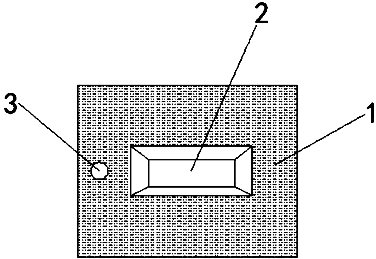
[0022] see Figure 1-2 , the present invention provides a technical solution: a steel casting mold with automatic clamping and positioning, including a lower mold base 1, a casting groove 2 is opened on the top of the lower mold base 1, and the top of the lower mold base 1 is located on the left side of the casting groove 2 There are bolt positioning holes 3 on the side, and connecting rods 4 are fixedly installed on the bottom of the left and right sides of t...


PUM


Abstract

The invention relates to the technical field of molds and discloses an automatic clamping and positioning rolled steel casting mold. The automatic clamping and positioning rolled steel casting mold comprises a lower mold base. The top of the lower mold base is provided with a casting groove. The position, far away from the casting groove, of the top of the lower mold base is provided with a bolt positioning hole. The bottoms of the left side and the right side of the lower mold base are both fixedly provided with connection rods. The ends, far away from the lower mold base, of the connection rods are movably connected with guide columns. Springs surrounding the outer surfaces of the connection rods are fixedly connected between the lower mold base and the guide columns. The tops of the inner sides of the guide columns are fixedly provided with positioning blocks. The inner sides of the positioning blocks are fixedly provided with positioning protruding points. The top of the lower moldbase is connected with an upper mold base in a buckled manner. The top of the upper mold base is further provided with a bolt through hole. The left side and the right side of the upper mold base areboth provided with positioning grooves. The clamping and positioning structure of the mold is simple, mold dismounting is convenient, a great amount of time is saved, and by means of a movable mold core, the mold can be used for casting of different types of rolled steel.

Description

technical field [0001] The invention relates to the technical field of molds, in particular to an automatic clamping and positioning steel casting mold. Background technique [0002] Molds are various molds and tools used in industrial production for injection molding, blow molding, extrusion, die-casting or forging forming, smelting, stamping, etc. to obtain the required products. In short, molds are tools used to make shaped objects , this kind of tool is composed of various parts, and different molds are composed of different parts. It mainly realizes the processing of the shape of the object through the change of the physical state of the formed material, known as the "mother of industry". [0003] At present, the molds on the market basically use multiple fixing screws or buckles for positioning. Such a structure is cumbersome and time-consuming to dismantle the mold. The fixed core structure greatly restricts the multi-profile function of the mold, making the mold func...

Claims


Application Information

Patent Timeline
Patent Type & Authority Applications(China)
IPC IPC(8): B22C9/06B22C9/00
CPCB22C9/067B22C9/00B22C9/064
Inventor 黎明
Owner 应城市砺安智能科技有限公司
Why Eureka
Try Eureka