
Cleaning device for floor surface

A technology for cleaning equipment and floors, applied in cleaning equipment, cleaning floors, applications, etc., can solve problems such as easy slipping, difficult dust accumulation structure, difficult to destroy dust structure, etc., to achieve easy removal, reduce slipping, and improve cleaning efficiency and effect Effect

Active Publication Date: 2018-11-13
嘉兴巨腾信息科技有限公司
View PDF7 Cites 6 Cited by
  • Summary
  • Abstract
  • Description
  • Claims
  • Application Information

AI Technical Summary

Problems solved by technology

[0003] Existing floor gap cleaners usually use air force to remove impurities in the gaps. Although they have achieved certain results, they have the following problems: First, the dust forms a hard plate structure in the process of accumulating layers, while the existing The cleaner directly injects the high-pressure gas vertically on the dust, which is equivalent to directly spraying on the plane of the plate, so it is difficult to destroy the structure of the dust; secondly, it is difficult to completely destroy the accumulation structure of the dust by simply using air force, and a variety of cleaning methods must be used In order to improve the cleaning effect and efficiency; the third, the existing cleaners are usually provided with wheels to facilitate walking on the floor, and then these wheels have insufficient friction with the ground, especially when walking on a smooth tile floor, it is easy to slip, so it is necessary to design New wheels capable of walking on slippery floors

Method used


Image

  • Cleaning device for floor surface
  • Cleaning device for floor surface
  • Cleaning device for floor surface

Examples


Embodiment Construction

[0028] The present invention will be further described in detail below in conjunction with the accompanying drawings, so that those skilled in the art can implement it with reference to the description.

[0029] Such as figure 1 , 2 , 3 and 4, a cleaning device for floor surfaces, comprising:

[0030] The car body 2 that can run along the surface of the floor 1, the car body 2 includes a chassis 3 arranged horizontally and wheels 4 arranged on both sides of the chassis, the wheels 4 support the chassis 3 from the surface of the floor 1 at a certain height distance, The height distance needs to be set according to the size of the cover body 9, so as to be able to set the cover body 9 under the chassis 3, wherein the wheel 4 includes a central shaft 5 and spokes 6, the chassis 3 is erected on the central shaft 5, and the chassis 3 Connect with the central shaft 5 through a bearing so that the central shaft 5 can rotate. The spokes 6 are curved rod-shaped structures. The spokes...


PUM

PropertyMeasurementUnit
Diameteraaaaaaaaaa
Diameteraaaaaaaaaa

Abstract

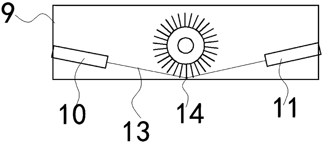
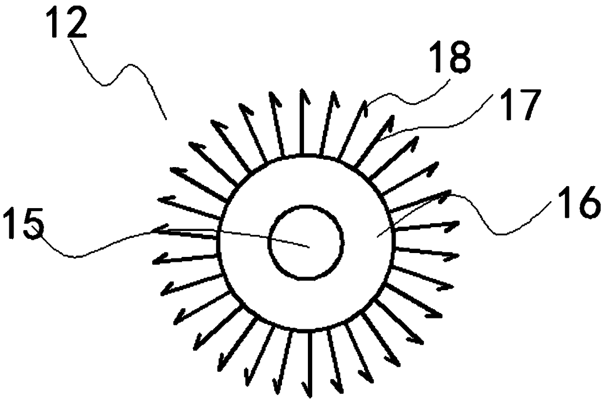
The invention discloses a cleaning device for the floor surface. The cleaning device comprises a car body, a cover body, an air injection assembly, a liquid spraying assembly and a brush assembly, wherein the car body comprises a chassis and a wheel. The wheel comprises a center shaft and spokes, the spokes are of a bent rod-shaped structure, the first ends of the spokes are fixed to the center shaft, the second ends are radiated outwards, a suction cup is fixed to the second of each spoke, a screw hole is formed in the center of the chassis, and a screw is matched with the screw hole; the upper end of the cover body is fixed to the screw, an opening in the lower end of the cover body is close to the floor surface, and a containing space is formed inside the cover body; the air injection assembly comprises an air pump and an air tap, the air tap is arranged inside the containing space, one end of the air tap is inclined downwards to point the floor, and the air pump is communicated with the air tap; the liquid spraying assembly comprises a hydraulic pump and a nozzle, the nozzle is arranged inside the containing space, one end of the nozzle is inclined downwards to point the floor,the hydraulic pump is communicated with the nozzle, and a liquid storage tank arranged on the chassis is communicated with the hydraulic pump; the air tap and the nozzle are arranged in a spaced mode; the brush assembly is arranged between the air tap and the nozzle.

Description

technical field [0001] The present invention relates to the technical field of cleaning equipment, more specifically, the present invention relates to a cleaning equipment for floor surface. Background technique [0002] There are horizontal and vertical splicing gaps on the surface of the wooden floor or tile floor. It is difficult for brooms, mops and conventional vacuum cleaners to clean the dust from these small gaps. As time goes by, the dust accumulates more and more, and finally accumulates and condenses into a stubborn structure. [0003] Existing floor gap cleaners usually use air force to remove impurities in the gaps. Although they have achieved certain results, they have the following problems: First, the dust forms a hard plate structure in the process of accumulating layers, while the existing The cleaner directly injects the high-pressure gas vertically on the dust, which is equivalent to directly spraying on the plane of the plate, so it is difficult to dest...

Claims


Application Information

Patent Timeline
IPC IPC(8): A47L11/292A47L11/40
CPCA47L11/292A47L11/40A47L11/4036A47L11/4072
Inventor 甘宜山
Owner 嘉兴巨腾信息科技有限公司
Learn More