
Electromagnetic coil

A technology of electromagnetic coils and winding parts, which is applied in the direction of circuits, transformers/inductor coils/windings/connections, electrical components, etc., which can solve the difficulty of automatic soldering, unstable connection reliability, and low production efficiency and other issues to achieve the effect of improving convenience and accuracy, low manufacturing cost and high production efficiency

Active Publication Date: 2020-07-10
江苏华阳智能装备股份有限公司
View PDF7 Cites 0 Cited by
  • Summary
  • Abstract
  • Description
  • Claims
  • Application Information

AI Technical Summary

Problems solved by technology

However, the electromagnetic coil with the above-mentioned structure has the following disadvantages. Due to the space position, the connection between the inner and outer leads of the winding and the end of the pin and the soldering of the connection cannot be automated or it is very difficult to automate. In the prior art All are manual operations, product quality is related to manual operation skills, connection reliability is unstable, production efficiency is low, and the corresponding cost is high

Method used


Image

  • Electromagnetic coil
  • Electromagnetic coil
  • Electromagnetic coil

Examples


Embodiment Construction

[0054]Embodiments of the present invention are described in detail below, examples of which are shown in the drawings, wherein the same or similar reference numerals designate the same or similar elements or elements having the same or similar functions throughout. The embodiments described below by referring to the figures are exemplary only for explaining the present invention and should not be construed as limiting the present invention.

[0055] In describing the present invention, it should be understood that the terms "center", "longitudinal", "transverse", "length", "width", "thickness", "upper", "lower", "front", " Back", "Left", "Right", "Vertical", "Horizontal", "Top", "Bottom", "Inner", "Outer", "Clockwise", "Counterclockwise", "Axial", The orientation or positional relationship indicated by "radial", "circumferential", etc. is based on the orientation or positional relationship shown in the drawings, and is only for the convenience of describing the present inventi...


PUM


Abstract

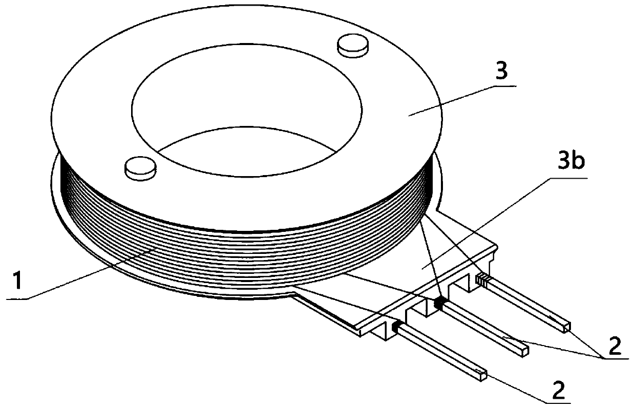
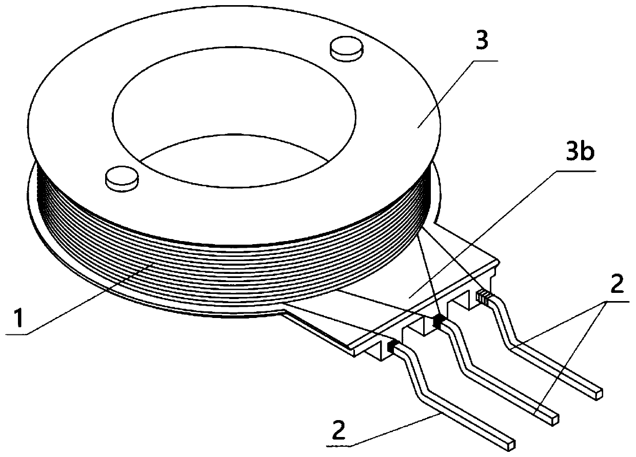
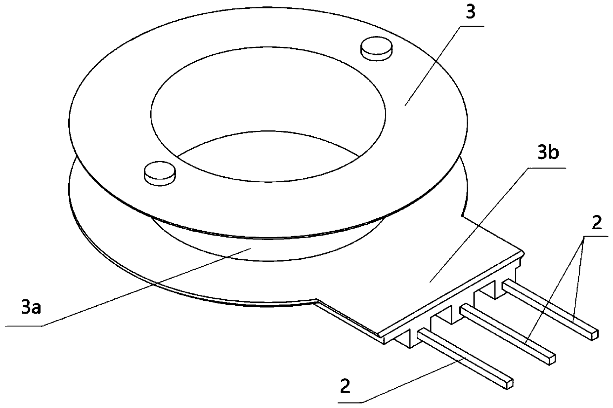
The invention discloses an electromagnetic coil which comprises two frameworks. Each framework comprises a winding part, two knife-edge-shaped parts, a holding part and a plurality of pins, wherein the winding part forms a columnar shape, the two knife-edge-shaped parts are arranged at the two ends of the winding part in parallel, the holding part is arranged on the periphery of one knife-edge-shaped part and is opposite to the other knife-edge-shaped part, the holding part comprises a plurality of protruding parts which are arranged at intervals in parallel, the protruding parts are connectedwith the knife-edge-shaped parts, every two adjacent protruding parts are separated from each other to form a notch part, and each protruding part is provided with a through hole running through theaxial direction of the winding part; the pins are inserted into the through holes respectively in the axial direction of the through holes, the two knife-edge-shaped parts with the holding part in thetwo frameworks are oppositely arranged, the protruding parts of one framework are inserted into the notch parts of the other framework, and the protruding parts of the other framework are inserted into the notch parts of one framework. The electromagnetic coil can improve the automation degree of winding and welding, and has the advantages of being high in production efficiency, low in manufacturing cost and the like.

Description

technical field [0001] The invention relates to an electromagnetic coil, in particular to a structure suitable for automatic wire winding and welding, which is connected with pins for electricity and winding wires. Background technique [0002] Existing electromagnetic coils usually consist of a skeleton, winding wires and pins. The skeleton usually has a pair of flange-shaped parts arranged in parallel, and a winding part arranged between the flange-shaped parts for winding the winding wire. There is a holding part for installing pins on the side of one end of the part, and the winding wire is connected to the pins. However, the electromagnetic coil with the above-mentioned structure has the following disadvantages. Due to the space position, the connection between the inner and outer leads of the winding and the end of the pin and the soldering of the connection cannot be automated or it is very difficult to automate. In the prior art All are manually operated, the produc...

Claims


Application Information

Patent Timeline
Patent Type & Authority Patents(China)
IPC IPC(8): H01F27/30H01F27/29H01F27/28H01F27/32
CPCH01F27/28H01F27/29H01F27/306H01F27/324
Inventor 许鸣飞杨国灿王少锋
Owner 江苏华阳智能装备股份有限公司
Learn More