
System and method for determining working point of all-optical PAM (Pulse Amplitude Modulation) regenerator

A regenerator, working point technology, applied in transmission systems, electromagnetic wave transmission systems, electrical components, etc., can solve the problems of low measurement efficiency, cumbersome operation, complicated measurement process, etc., to achieve simple measurement system, easy method, and high test efficiency. Effect

Active Publication Date: 2018-11-06
UNIV OF ELECTRONICS SCI & TECH OF CHINA
View PDF4 Cites 2 Cited by
  • Summary
  • Abstract
  • Description
  • Claims
  • Application Information

AI Technical Summary

Benefits of technology

This patented technology allows for efficient testing of an optically active polymer (PMA) material used within certain technical devices such as light valves or displays that use this type of material. It achieves these results by measuring just two different states: 1) its absorption properties when excited at specific wavelengths, 2) how well it responded to lasers while being driven off under constant current conditions.

Problems solved by technology

Technological Problem: Current methods involve measuring the work done on an opto-isolating device called an all-Optical Regulator Point ("AOPP") through complex procedures involving multiple measurements over time. These techniques can lead to reduced accuracy due to variations between different devices' performance characteristics caused during manufacture processes.

Method used


Image

  • System and method for determining working point of all-optical PAM (Pulse Amplitude Modulation) regenerator
  • System and method for determining working point of all-optical PAM (Pulse Amplitude Modulation) regenerator
  • System and method for determining working point of all-optical PAM (Pulse Amplitude Modulation) regenerator

Examples


Embodiment

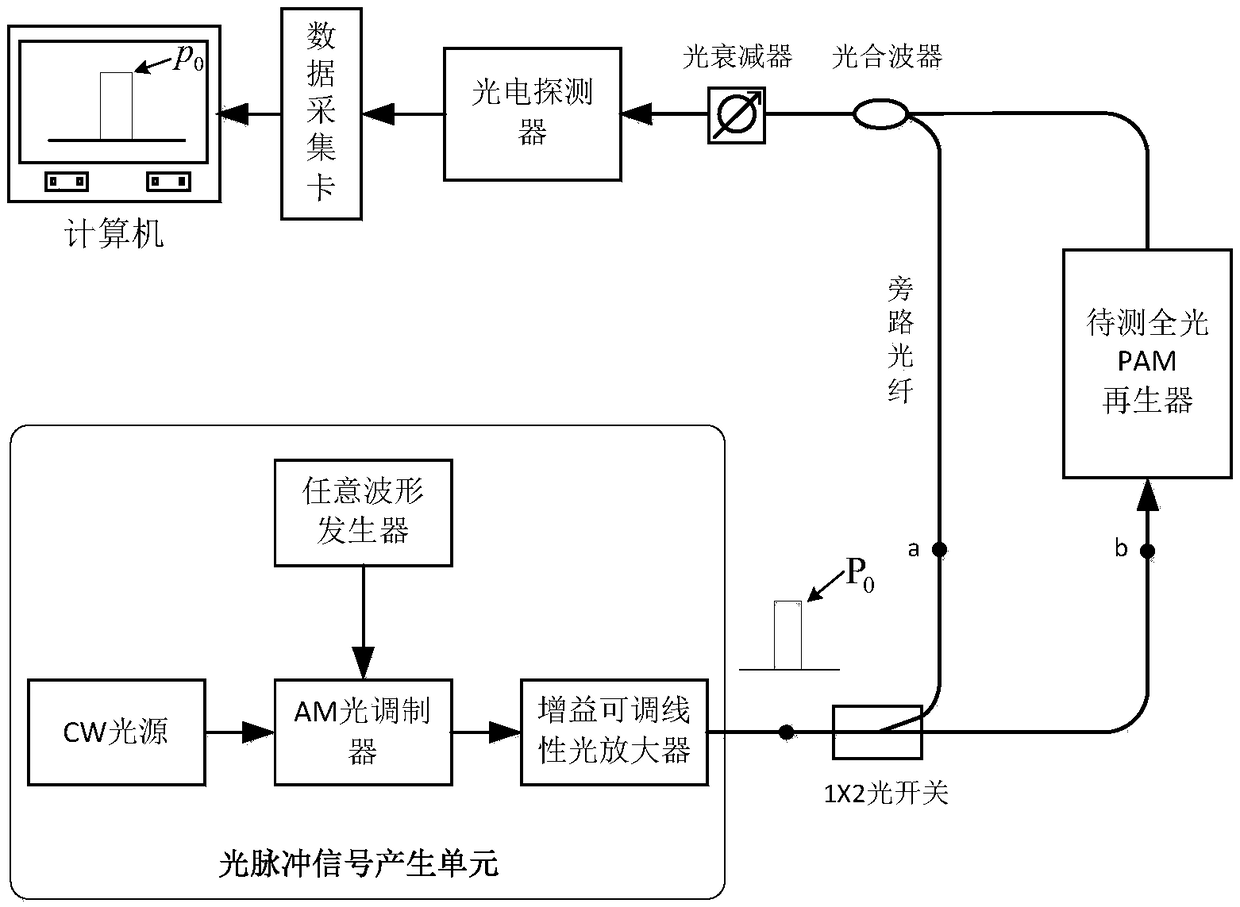
[0038] figure 1 It is a principle block diagram of the system for measuring the working point of the all-optical PAM regenerator in the present invention.

[0039] In this example, if figure 1 As shown, a system for measuring the operating point of an all-optical PAM regenerator of the present invention includes: an optical pulse signal generating unit, a 1x2 optical switch, a bypass fiber, an all-optical PAM regenerator to be tested, an optical multiplexer, an optical attenuator, a photoelectric Detectors, data acquisition cards and computers for off-line data processing;

[0040] Among them, the optical pulse signal generating unit includes an arbitrary waveform generator, a continuous light (CW) light source, an amplitude (AM) optical modulator and a gain-adjustable linear optical amplifier; by setting different parameters of the arbitrary waveform generator, the optical pulse signal is generated The unit can output rectangular and trapezoidal optical pulse test signals; ...


PUM


Abstract

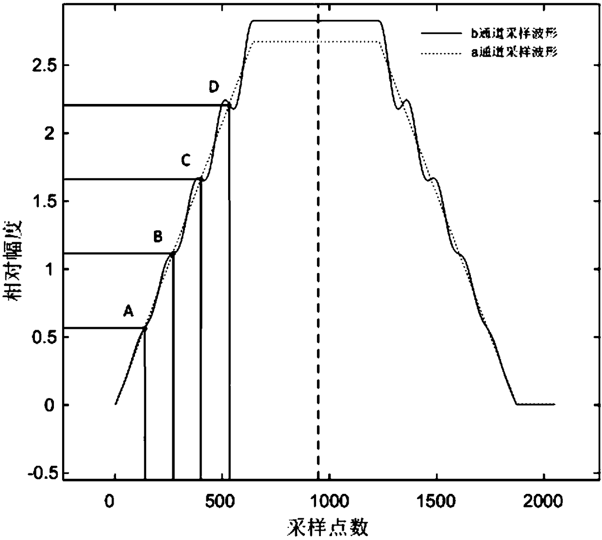
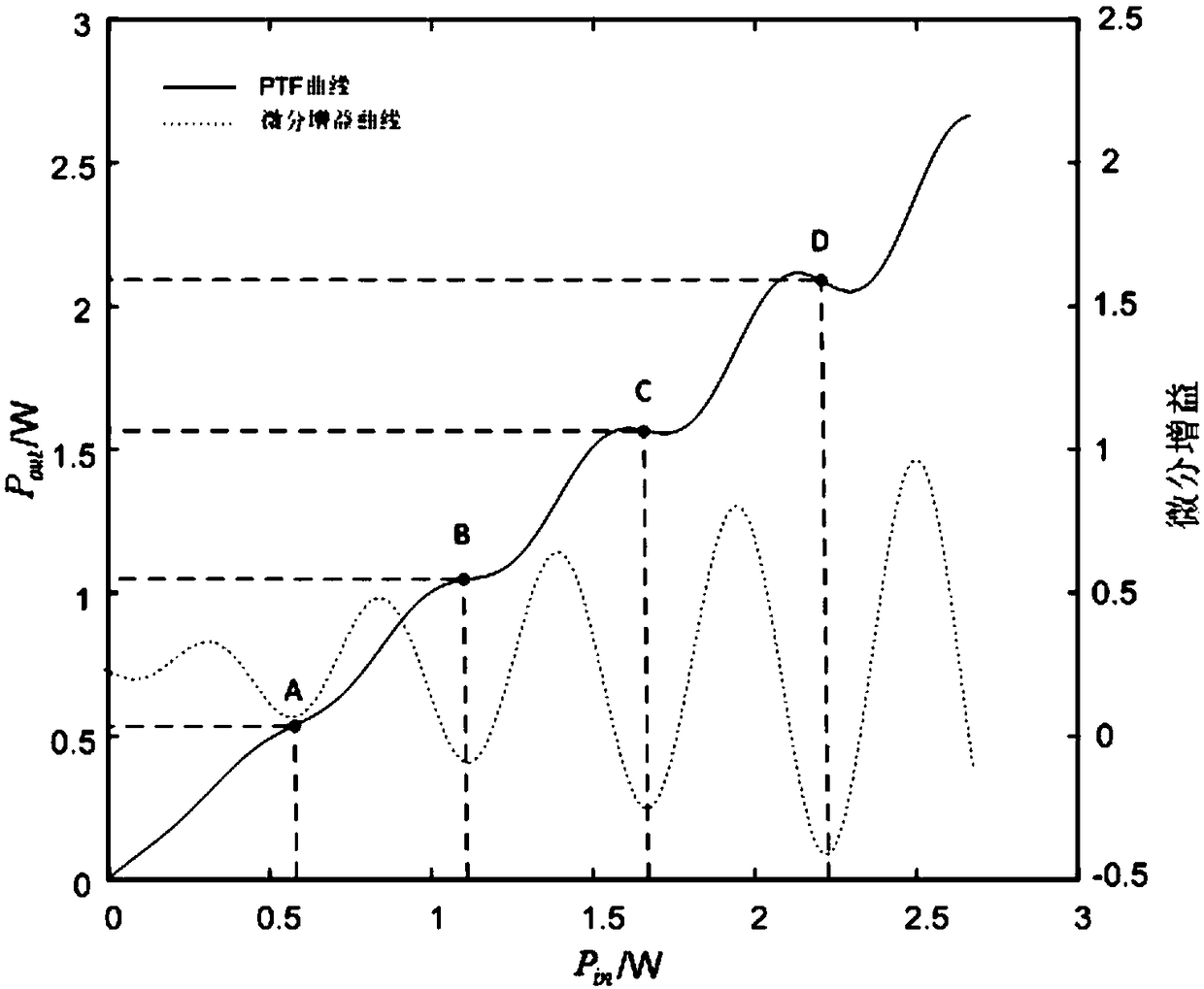
The invention discloses a system and method for determining a working point of an all-optical PAM (Pulse Amplitude Modulation) regenerator. The method comprises the following steps: firstly, generating rectangular and trapezoidal periodic test signals by an optical pulse generating unit respectively, and switching to a bypass optical fiber and an all-optical PAM regenerator to be determined in sequence by a 1x2 optical switch; secondly, connecting a photo-synthesizer and an optical attenuator to a photoelectric detector, and performing analog-digital conversion on a photoelectric conversion output signal by a data acquisition card; and finally, finishing alignment of an output pulse waveform, calculation of an input/output power transfer function (PTF) and determination of the working point of the all-optical PAM regenerator by offline computer processing.

Description


Claims


Application Information

Patent Timeline
Owner UNIV OF ELECTRONICS SCI & TECH OF CHINA
Learn More