
Display panel and display apparatus

A technology for display panels and substrate substrates, which is used in printing image acquisition, instruments, computing, etc., can solve problems such as crosstalk, reduce fingerprint identification accuracy, and fingerprint identification light deflection signals, so as to reduce signal crosstalk and improve fingerprint identification accuracy. Effect

Active Publication Date: 2018-11-06
WUHAN TIANMA MICRO ELECTRONICS CO LTD
View PDF7 Cites 24 Cited by
  • Summary
  • Abstract
  • Description
  • Claims
  • Application Information

AI Technical Summary

Problems solved by technology

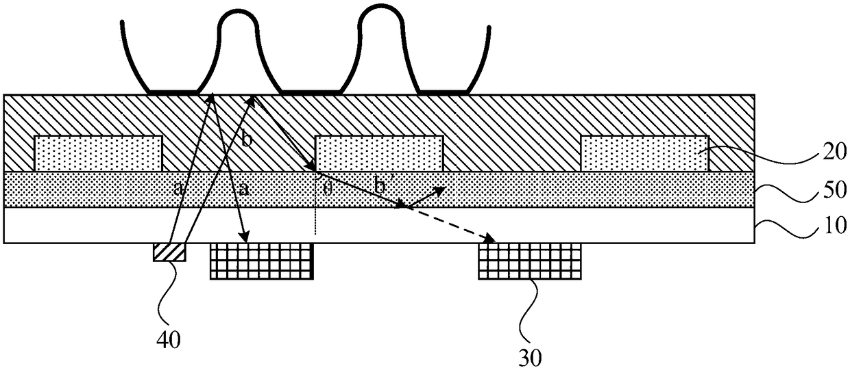
The currently popular in-screen fingerprint recognition system is to install the fingerprint recognition module under the organic light-emitting diode (OLED) display panel. The light emitted by the fingerprint recognition light source is reflected by the fingerprint and then passes through the display panel to reach the fingerprint recognition module for fingerprint recognition. However, due to the existence of wiring, thin-film transistors and other structures in the display panel, the scattering of light by these structures may cause large-angle deflection of fingerprint recognition light, causing signal crosstalk and reducing the accuracy of fingerprint recognition.

Method used


Image

  • Display panel and display apparatus
  • Display panel and display apparatus
  • Display panel and display apparatus

Examples


Embodiment Construction

[0028] The present invention will be further described in detail below in conjunction with the accompanying drawings and embodiments. It should be understood that the specific embodiments described here are only used to explain the present invention, but not to limit the present invention. In addition, it should be noted that, for the convenience of description, only some structures related to the present invention are shown in the drawings but not all structures.

[0029] In the field of mobile phones, with the concept of "full screen", the application of optical fingerprint recognition technology is becoming more and more extensive. The basic principle of optical fingerprint identification technology is: the light emitted by the light source in the display panel is irradiated on the touch subject (such as a finger), and reflected by the touch subject, the formed reflected light (i.e. fingerprint signal light) is transmitted to the fingerprint identification module. The fing...


PUM


Abstract

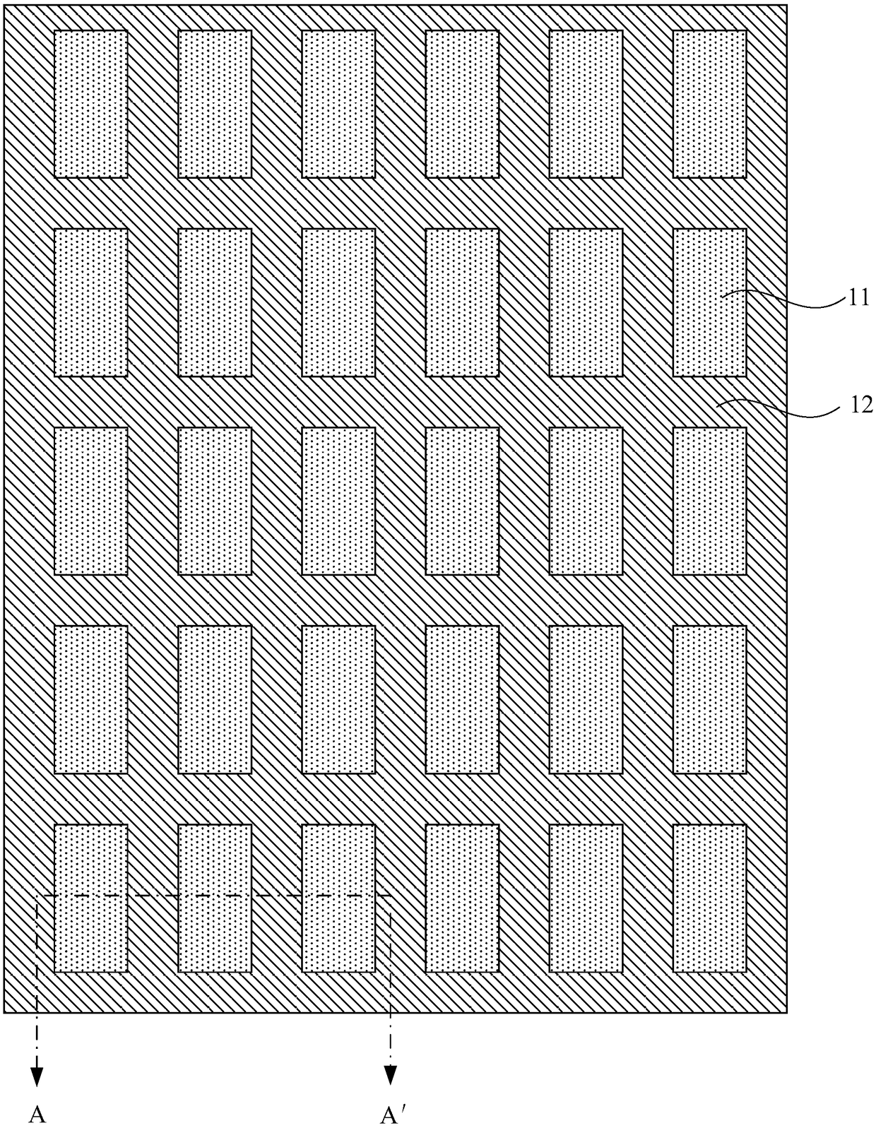
The embodiment of the invention discloses a display panel and a display apparatus. The display panel includes a substrate, a plurality of light-emitting units formed on the substrate, at least one fingerprint identification module, a fingerprint identification light source and a reflection layer wherein the substrate includes an opening region and a non-opening region surrounding the opening region; the vertical projection of the each light-emitting unit on the substrate is located in the opening region; the vertical projection of the fingerprint identification module on the substrate is located in the non-opening region; the light emitted from the fingerprint identification light source is reflected by a touch main body, and then is incident on the fingerprint identification module to perform fingerprint identification; and the reflection layer is formed between the light-emitting units and the fingerprint identification module for preventing the light that the angle of inclination ofthe light is greater than the preset angle being incident on the fingerprint identification module. The display panel solves the problem that the light that the angle of inclination of the light is greater than the preset angle causes crosstalk of the fingerprint identification signal, and can achieve the effect of improving the fingerprint identification accuracy of the display panel.

Description

technical field [0001] Embodiments of the present invention relate to display technologies, and in particular, to a display panel and a display device. Background technique [0002] Fingerprint is an innate and unique biological feature. It consists of a series of ridges and valleys on the skin surface of the fingertips to form details such as arches, left-handed, right-handed, and spirals. With the development of fingerprint recognition technology, Various display devices with fingerprint recognition functions appear on the market, such as mobile phones, tablet computers, and smart wearable devices. [0003] With people's requirements for performance and appearance of various display devices with fingerprint recognition functions, in-screen fingerprint recognition technology has become a current research hotspot. The current popular in-screen fingerprint recognition system is to install the fingerprint recognition module under the organic light-emitting diode (OLED) displa...

Claims


Application Information

Patent Timeline
Patent Type & Authority Applications(China)
IPC IPC(8): G06K9/00
CPCG06V40/1318
Inventor 王永志彭涛
Owner WUHAN TIANMA MICRO ELECTRONICS CO LTD
Learn More