
Solar lighting device

A lighting device and solar energy technology, applied in the field of lighting, can solve the problems of low light conversion efficiency and achieve the effect of reducing damage and preventing dead ends

Inactive Publication Date: 2018-11-06
金华市盛缇智能科技有限公司
View PDF0 Cites 0 Cited by
  • Summary
  • Abstract
  • Description
  • Claims
  • Application Information

AI Technical Summary

Problems solved by technology

[0003] Solar lighting uses solar energy as energy, realizes photoelectric conversion through solar cells, uses batteries to save and store electric energy during the day, and supplies power to electric light sources through controllers at night to achieve the required functional lighting. In modern buildings, lighting is also widely used. application, and the lighting is often installed on the balcony and under the eaves. In order to prevent the influence of bad weather, many photovoltaic panels are directly attached to the wall. However, due to the influence of the angle of light, the photovoltaic panels will cause low light conversion efficiency.

Method used


Image

  • Solar lighting device
  • Solar lighting device

Examples


Embodiment Construction

[0018] All features disclosed in this specification, or steps in all methods or processes disclosed, may be combined in any manner, except for mutually exclusive features and / or steps.

[0019] Any feature disclosed in this specification, unless specifically stated, can be replaced by other alternative features that are equivalent or have similar purposes. That is, unless expressly stated otherwise, each feature is one example only of a series of equivalent or similar features.

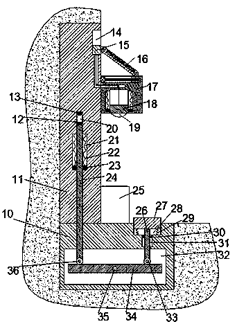
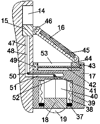
[0020] Such as Figure 1 to Figure 2As shown, a solar lighting device of the device of the present invention includes a vertical plate 11 fixedly installed in the wall and a horizontal plate 10 fixedly installed in the ground, and the left side of the upper end surface of the horizontal plate 10 is below the vertical plate 11. The end faces are fixedly connected, a transmission chamber 32 is provided in the transverse plate 10, a first sliding groove 28 with the opening facing upward is arranged in t...


PUM


Abstract

The invention discloses a solar lighting device. The solar lighting device comprises a vertical plate fixedly installed in a wall and a transverse plate fixedly installed in the ground. The left sideof the upper end face of the transverse plate is fixedly connected with the lower end face of the vertical plate. The transverse plate is internally provided with a transmission cavity. The transverseplate is internally provided with a first sliding groove with an upward opening. The first sliding groove is internally provided with a pedal in a sliding manner. The upper end face of the transverseplate is fixedly provided with a laundry tray fixedly connected with the left end face of the vertical plate. A first communicating groove communicating with the first sliding groove and the transmission cavity is formed between the first sliding groove and the transmission cavity. The first communicating groove is internally provided with an up-down extending first top rod in a sliding manner, the upper end of the first top rod is fixedly connected with the bottom end of the pedal, and the lower end of the first top rod extends into the transmission cavity. The vertical plate is internally provided with a second sliding groove with a downward opening, the second sliding groove penetrates the transverse plate and communicates with the transmission cavity, and the second sliding groove isinternally provided with a second top rod in a sliding manner.

Description

technical field [0001] The invention relates to the technical field of lighting, in particular to a solar lighting device. Background technique [0002] China is a country that consumes a lot of energy, mainly coal, oil, and natural gas. These raw materials have limited reserves and are non-renewable. Moreover, energy consumption emits carbon dioxide and sulfur oxides at the same time, causing global warming and acid rain, and damaging the environment. Therefore, the development and utilization of renewable energy is of great significance to ensure energy security, protect the ecological environment, and achieve sustainable development. Solar lighting has developed rapidly, and its devices have almost covered the entire lighting field. The market demand for solar lighting products is increasing day by day, and the requirements for product quality are also getting higher and higher. [0003] Solar lighting uses solar energy as energy, realizes photoelectric conversion thr...

Claims


Application Information

Patent Timeline
Patent Type & Authority Applications(China)
IPC IPC(8): F21S9/03F21V15/00F21V19/02F21V23/04F21V23/06F21V33/00H02S20/30
CPCF21S9/03F21V15/00F21V19/02F21V23/04F21V23/06F21V33/004H02S20/30Y02E10/50
Inventor 黄政
Owner 金华市盛缇智能科技有限公司
Learn More