Novel breather valve

A breathing valve, a new type of technology, applied in the field of breathing valves, can solve problems such as increasing equipment investment costs, reducing the service life of breathing valves, and poor sealing of breathing valves, so as to reduce steam leakage loss, eliminate hidden dangers of personnel injury, and improve equipment. The effect of occupancy rate

Pending Publication Date: 2018-11-06
李文博
View PDF0 Cites 0 Cited by
  • Summary
  • Abstract
  • Description
  • Claims
  • Application Information

AI Technical Summary

Problems solved by technology

[0002] The original breathing valve is spring-type, and it works in the environment of high temperature, high pressure and corrosive smoke for a long time. This harsh environment will reduce the service life of the breathing valve; on the one hand, some corrosive smoke washes and corrodes the sealing surface of the breathing valve On the other hand, the spring of the breathing valve will be corroded, causing the sealing of the breathing valve to be loose, resulting in steam leakage, increasing the boiler supply water, and when people are close to the steam valve, it is easy to cause burns when they suddenly blow soot; at the end of soot blowing As the remaining part of the steam in the casing condenses into water and flows back out of the breathing valve, it is easy to freeze in the cold winter, threatening personal safety; the breathing valve leaks need to be replaced frequently, increasing equipment investment costs

Method used


Image

  • Novel breather valve
  • Novel breather valve
  • Novel breather valve

Examples


Embodiment Construction

[0015] The present invention is described in further detail now in conjunction with accompanying drawing. These drawings are all simplified schematic diagrams, which only illustrate the basic structure of the present invention in a schematic manner, so they only show the configurations related to the present invention.

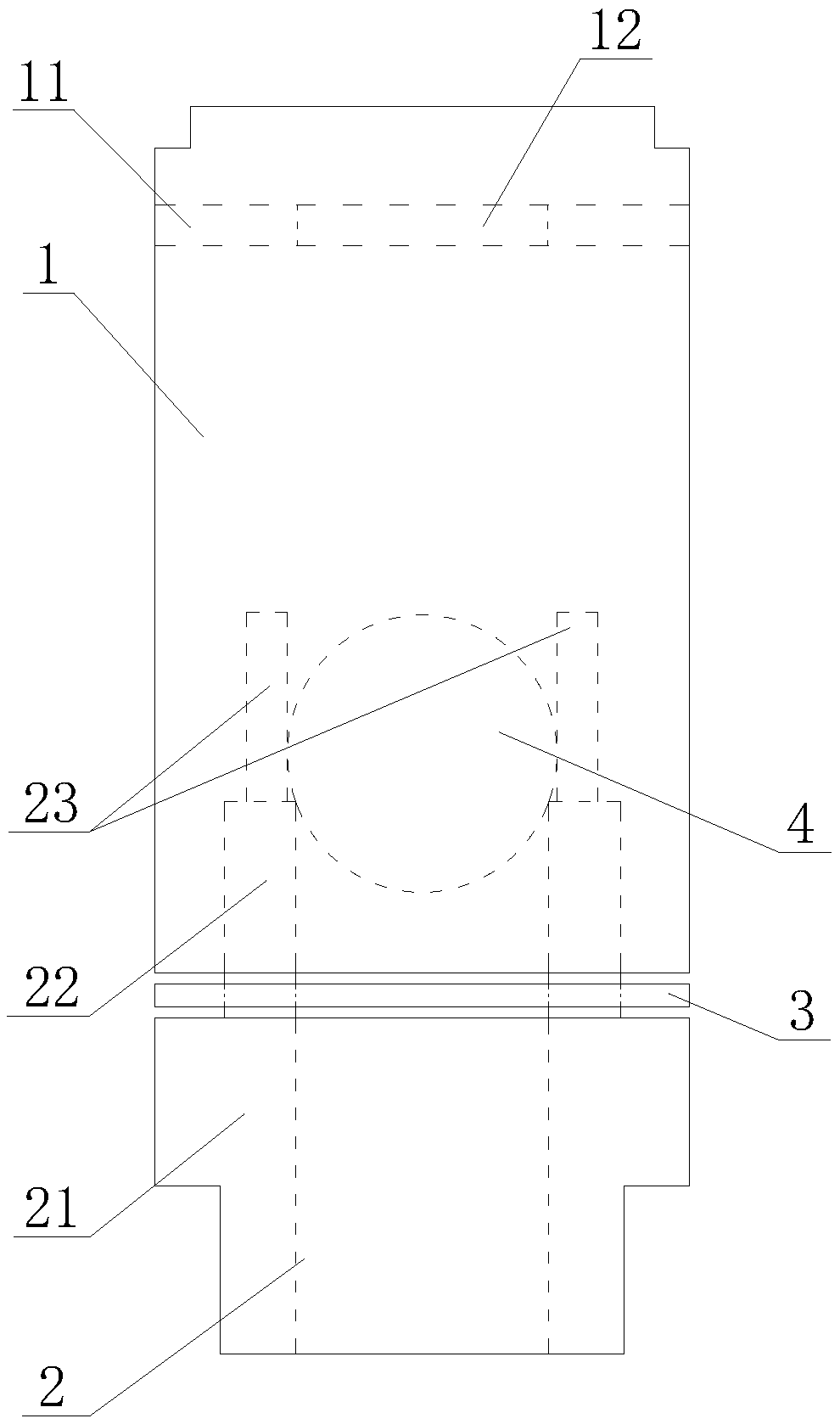
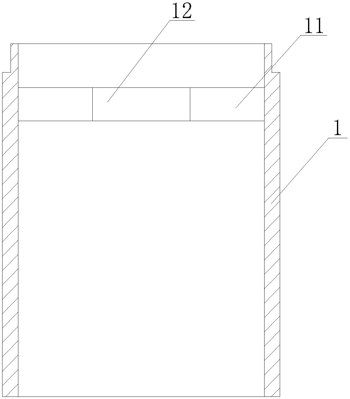
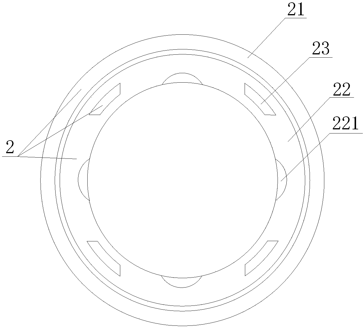
[0016] Such as Figure 1-4 A new type of breathing valve shown includes a cylinder body 1, a hollow lower end cover 2, a sealing sheet 3 and a sphere 4, the sealing sheet 3 is located between the cylinder body 1 and the lower end cover 2, and the steam outlet of the cylinder body 1 is set There is a baffle 11, internal threads are provided on the inner wall of the cylinder body 1, a round hole 12 is opened in the center of the baffle 11, and the lower end cover 2 has a steam entry end 21, a steam passing thread head 22 and four stoppers Riser 23, limit riser 23 is evenly respectively arranged on the port of threaded head 22 tops, and the end of threaded head ...


PUM


Abstract

The invention discloses a novel breather valve. The novel breather valve comprises a cylinder body, a hollow lower end cover, a sealing piece and a ball body. The sealing piece is located between thecylinder body and the lower end cover, a baffle is arranged in a steam outlet of the cylinder body, an internal thread is arranged on the inner wall of the cylinder body, and a circular hole is formedin the center position of the baffle. The lower end cover is provided with a end head for entering of steam, a threaded head for penetrating of the steam and at least two limiting vertical plates, the limiting vertical plates are uniformly and separately arranged on an end opening of the top end of the threaded head, the tail end of the threaded head is connected with the end head, and at least two circular arc grooves are uniformly formed downwards in the top end of the inner hole wall of the threaded head. The ball body is placed at the end opening position of the top end of the threaded head and carries out limiting on the threaded head through the limiting vertical plates, the baffle is located above the limiting vertical plates, the circular arc grooves enable a gap to be formed between the ball body and the inner hole wall of the threaded head, and the diameter of the ball body is greater than that of a circular hole and an inner hole of the threaded head. According to the novelbreather valve, the ball body is used for sealing, and the sealing performance is good; and the sealing piece is convenient to disassembly and assembly, and the replacement cost of equipment is reduced.

Description

technical field [0001] The invention relates to the technical field of breathing valves, in particular to a novel breathing valve which is easy to assemble and disassemble and prolongs the service life. Background technique [0002] The original breathing valve is spring-type, and it works in the environment of high temperature, high pressure and corrosive smoke for a long time. This harsh environment will reduce the service life of the breathing valve; on the one hand, some corrosive smoke washes and corrodes the sealing surface of the breathing valve On the other hand, the spring of the breathing valve will be corroded, causing the sealing of the breathing valve to be loose, resulting in steam leakage, increasing the boiler supply water, and when people are close to the steam valve, it is easy to cause burns when blowing soot suddenly; at the end of soot blowing As the remaining part of the steam in the casing condenses into water and flows back from the breathing valve, i...

Claims


Application Information

Patent Timeline
Patent Type & Authority Applications(China)
IPC IPC(8): F16K17/12F16K17/164F16K27/02
CPCF16K17/12F16K17/164F16K27/0245
Inventor 李文博
Owner 李文博
Why Eureka
Try Eureka