
Automatic roadblock placing device

A technology for placing devices and roadblocks, applied in the field of automatic roadblock placement devices, can solve problems such as difficulty in helping patients get up, cumbersome control logic, etc., and achieve the effects of reduced promotion and application, reliable connection, and convenient detection and maintenance.

Inactive Publication Date: 2018-11-06
管秋霞
View PDF5 Cites 7 Cited by
  • Summary
  • Abstract
  • Description
  • Claims
  • Application Information

AI Technical Summary

Problems solved by technology

[0005] The purpose of the present invention is to solve the common problems in the existing medical anti-decubitus beds that it is difficult to prevent the patient's skin from being under pressure in an all-round way, it is difficult to help the patient to get up, turn over and other actions, and the control logic is cumbersome. A roadblock automatic placing device

Method used


Image

  • Automatic roadblock placing device
  • Automatic roadblock placing device
  • Automatic roadblock placing device

Examples


Embodiment Construction

[0049] The present invention is described in detail below in conjunction with accompanying drawing:

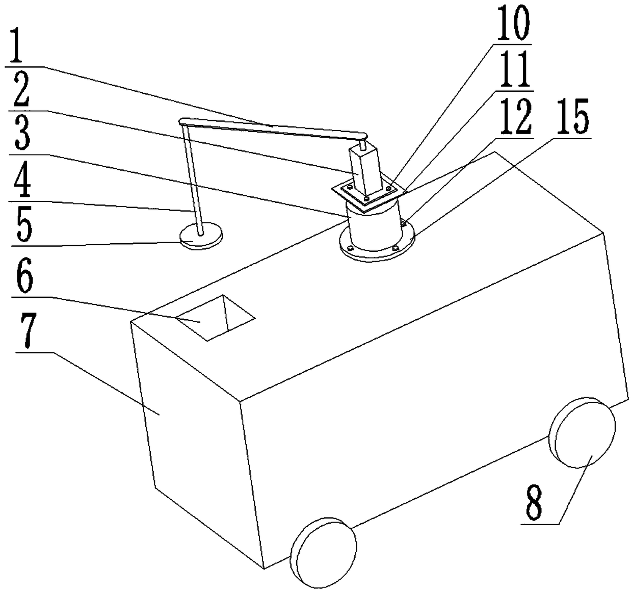
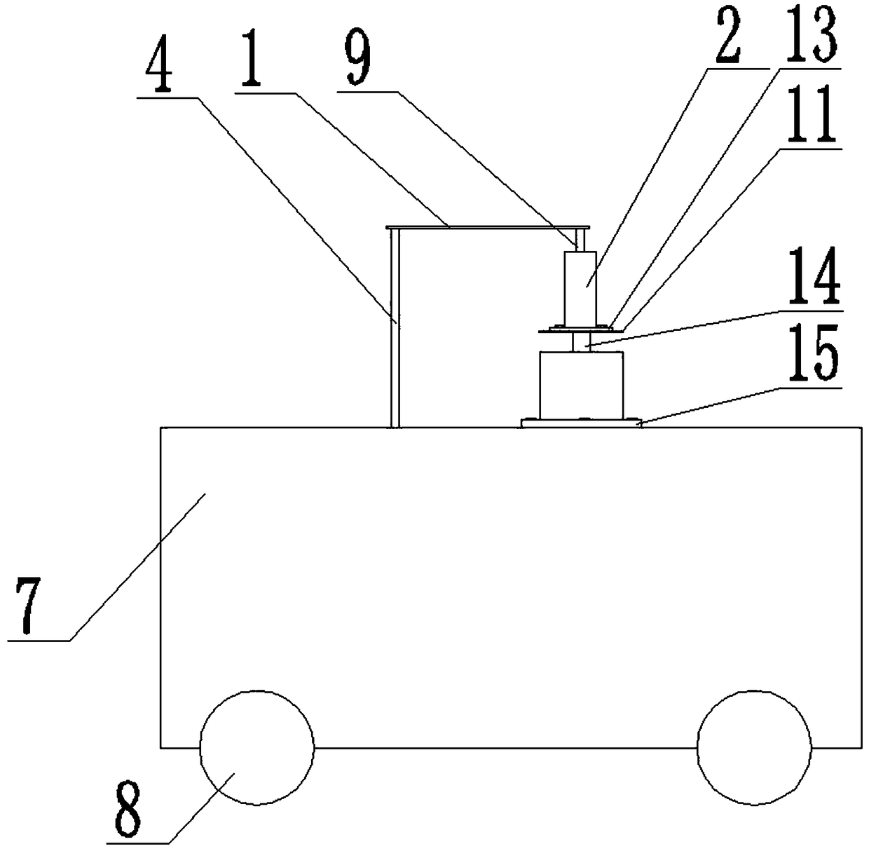
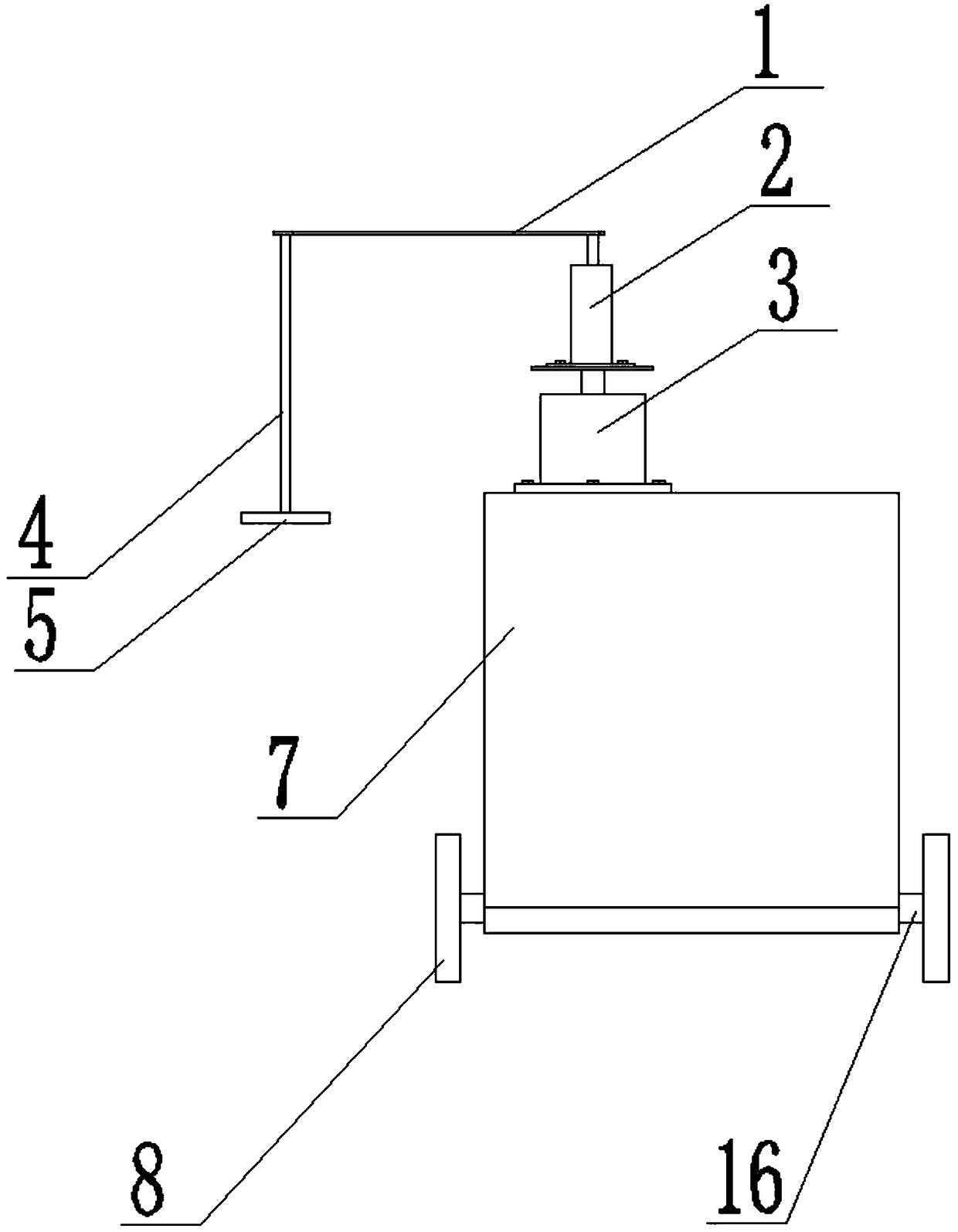
[0050] refer to Figure 1 to Figure 9A device for automatically placing roadblocks provided by the present invention includes a vehicle body 7, an electric cylinder 2 and a first motor 3 are fixed on the top of the main body of the vehicle body 7, wheels 8 and axles 16 are arranged on the bottom of the vehicle body 7, and a bottom plate 19 is provided inside the vehicle body 7. The upper side of the base plate 19 is provided with a second motor 21 and a first gear 22, the first gear 22 meshes with the chain 23, the chain 23 meshes with the second gear 25, and the second gear 25 is arranged on the end of the input shaft 39 of the reducer The output shaft 42 of the reducer drives the second rotary shaft 48 and the second friction cylinder 29 to perform rotary motion. The second friction cylinder 29 is in contact with the transmission belt 17 and drives it to move. A plurality of...


PUM


Abstract

The invention discloses an automatic roadblock placing device in order to solve the problems that a roadblock cannot be fully automatically and efficiently placed and control logic is tedious in the prior art. The automatic roadblock placing device comprises a vehicle body. An electric cylinder and a first motor are fixed to the top of a main body of the vehicle body. Wheels and axles are arrangedat the bottom of the vehicle body. A bottom board is arranged in the vehicle body. A second motor and a first gear are arranged on the upper side of the bottom board. The first gear is engaged with achain. The chain is engaged with a second gear. The second gear is arranged at the end of an input shaft of a speed reducer. An output shaft of the speed reducer drives a second rotary shaft and a second friction barrel to rotate. The second friction barrel makes contact with a conveyor belt and drives the conveyor belt to move. Multiple fixed magnetic discs are arranged on the upper side of theconveyor belt and attract a lower magnetic board at the bottom of the roadblock. A longitudinal rod is driven through motion of the electric cylinder, an attraction magnetic disc attracts an upper magnetic board at the top of the roadblock, so that an automatic roadblock placing function is achieved, application and popularization of the device are facilitated, and meanwhile the achieving cost isreduced.

Description

technical field [0001] The invention belongs to the field of road administration engineering, in particular to a device for automatically placing roadblocks. Background technique [0002] Barricades refer to obstacles placed on the road. Roadblock is a kind of facility for road traffic isolation and warning. It is generally used for temporary isolation and division of road maintenance construction. With the rapid development of my country's transportation industry, the new situation has higher and stricter requirements for the layout of roadblocks. [0003] At present, in the maintenance of domestic traffic roads, the roadblocks are mainly arranged manually, that is, the operators place the roadblocks one by one to the designated position on the traffic. This way of roadblock arrangement leads to a long time-consuming and uneven layout And there are hidden dangers of traffic accidents for operators. [0004] Chinese patent announcement number CN205636552U, public date is 2...

Claims


Application Information

Patent Timeline
IPC IPC(8): E01F9/70
CPCE01F9/70
Inventor 管秋霞
Owner 管秋霞
Learn More