Speed bump mounting device

A technology for installation devices and speed bumps, which is applied in roads, road signs, traffic signals, etc., can solve the problems of unfavorable health of workers, delay of installation progress, and low installation efficiency, so as to protect health, improve installation efficiency, and ensure installation progress effect

Inactive Publication Date: 2018-11-06
段欣彤
View PDF0 Cites 12 Cited by
  • Summary
  • Abstract
  • Description
  • Claims
  • Application Information

AI Technical Summary

Problems solved by technology

[0004] In view of the above situation, in order to overcome the defects of the prior art, the present invention provides a speed bump installation device, which effectively solves the problem of low installation efficiency and high labor intensity when the current speed bump is installed, which is not conducive to the health of workers and delays Problems with the installation progress

Method used


Image

  • Speed bump mounting device
  • Speed bump mounting device
  • Speed bump mounting device

Examples


Embodiment Construction

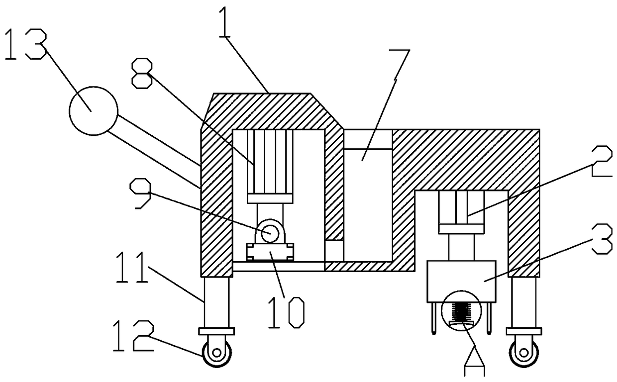
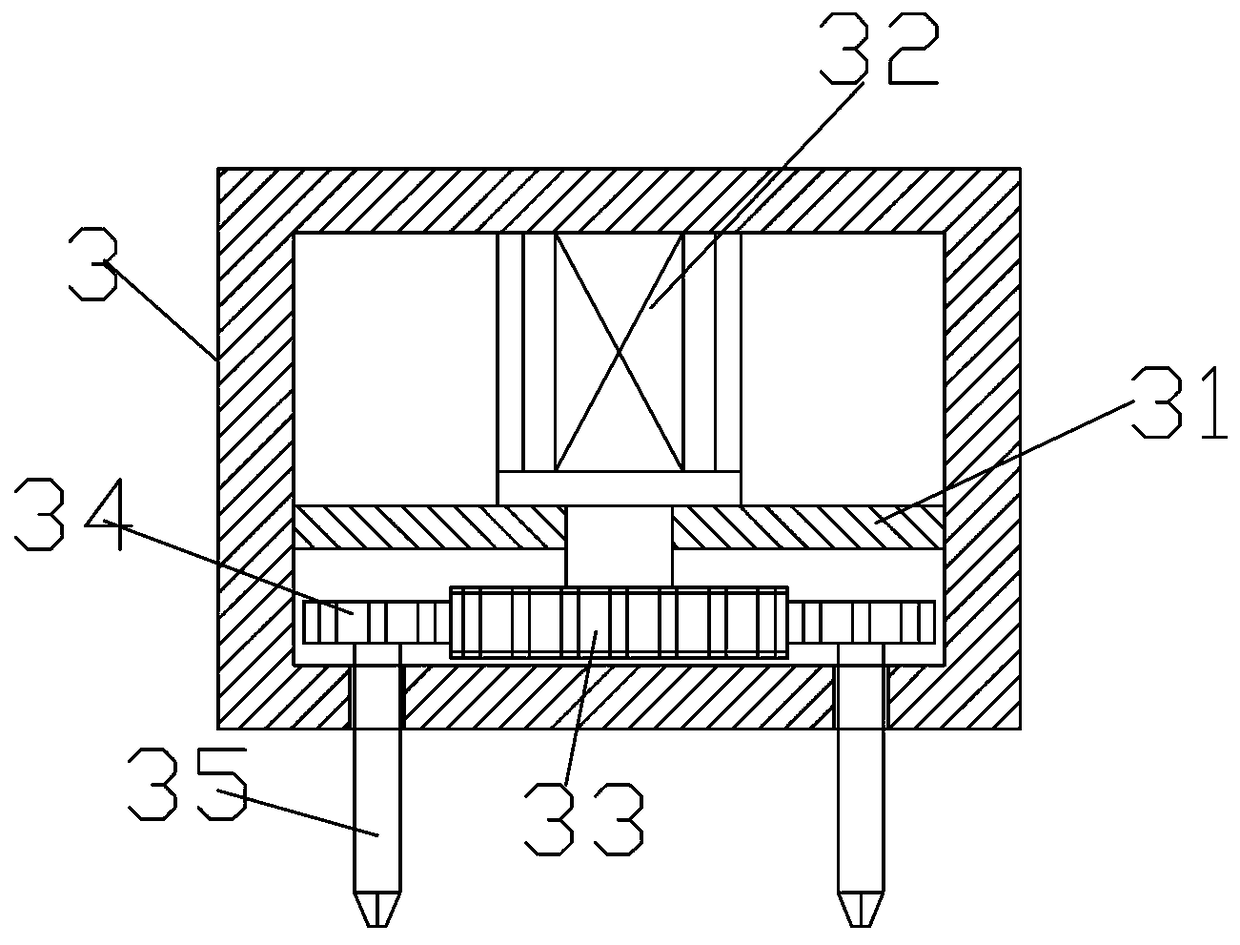
[0013] Attached below Figure 1-4 The specific implementation of the present invention will be described in further detail.

[0014] by Figure 1-4 Given that the present invention includes a mounting frame 1, a MPT63 pressurized cylinder 2 is fixed at the middle of one side of the mounting frame 1, a punch assembly 3 is fixed at the bottom end of the MPT63 pressurized cylinder 2, and a partition 31 is fixed at the bottom of the punch assembly 3, A GSR7.2-1 motor 32 is installed inside the punching assembly 3 through the middle of the partition 31. The bottom end of the GSR7.2-1 motor 32 is fixed with a first gear 33, and both ends of the first gear 33 are connected with a second gear 34. The bottom end of the second gear 34 penetrates through the bottom end of the punching assembly 3 and an electric rotor 35 is fixed at the bottom end. The bottom end of the punching assembly 3 is fixed with a telescopic rod 4, the bottom end of the telescoping rod 4 is installed with an arc pla...


PUM


Abstract

The invention discloses a speed bump mounting device. The problems that the mounting efficiency is low, the labor intensity is large, an existing speed bump is not beneficial for health of workers, and the mounting progress is delayed during mounting the existing speed bump are effectively solved. The speed bump mounting device comprises a mounting frame; a pressurized cylinder is fixed at the middle part of one side of the mounting frame; a perforating assembly is fixed at the bottom end of the pressurized cylinder; a partition plate is fixed on the internal side of the bottom of the perforating assembly; a motor is mounted at the part, running through the middle part of the partition plate, of the internal side of the perforating assembly; a first gear is fixed at the bottom end of the motor; second gears are connected to both the two ends of the first gear; electric drill bits are fixed at parts, running through the bottom end of the perforating assembly, of the middle parts of thebottom ends of the second gears; a telescopic rod is fixed at the middle part of the bottom end of the perforating assembly; an arc plate is mounted at the bottom end of the telescopic rod; a spring sleeves the part, between the perforating assembly and the arc plate, of the external side of the telescopic rod; a bolt box is mounted at the middle part of the mounting frame; a hydraulic cylinder isfixed at the upper part of the other side of the mounting frame; and an electric turntable is mounted at the bottom end of the hydraulic cylinder.

Description

Technical field [0001] The invention relates to the technical field of deceleration belt devices, in particular to a deceleration belt installation device. Background technique [0002] Speed ​​bumps are transportation facilities that are installed on highways to slow down vehicles passing by. They are generally strip-shaped or point-shaped. The material is mainly rubber or metal. They are usually yellow and black to attract visual attention. The road surface is slightly arched in order to achieve the purpose of vehicle deceleration. It is generally set at road crossings, industrial and mining enterprises, schools, residential quarters, and other road sections that require vehicles to slow down and road sections that are prone to traffic accidents. They are used to slow down motor vehicles and non-motor vehicles. A new type of special traffic safety setting for driving speed. The deceleration belt greatly reduces the accidents at various traffic intersections. It is a new type of...

Claims


Application Information

Patent Timeline
Patent Type & Authority Applications(China)
IPC IPC(8): E01F9/529E01F9/70
CPCE01F9/529E01F9/70
Inventor 段欣彤
Owner 段欣彤
Why Eureka
Try Eureka