
Powder feeding device capable of realizing powder gradient change and for laser cladding

A technology of powder feeding device and gradient change, which is applied in the field of powder feeding device, can solve the problems of lower production efficiency, low powder utilization efficiency, blockage of laser cladding head of powder feeding pipeline, etc., to improve the degree of uniformity, improve utilization efficiency, The effect of improving quality

Active Publication Date: 2018-11-06
FUJIAN UNIV OF TECH
View PDF7 Cites 5 Cited by
  • Summary
  • Abstract
  • Description
  • Claims
  • Application Information

AI Technical Summary

Problems solved by technology

[0004] The technical problem to be solved by the present invention is to provide a powder feeding device for laser cladding that can realize powder gradient changes, which can solve the problem of blockage of the powder feeding pipeline and laser cladding head caused by powder feeding in the prior art, and reduce the At the same time, problems such as low powder utilization efficiency and the inability to realize real-time gradient changes of various powders during the cladding process can effectively improve the quality of cladding forming

Method used


Image

  • Powder feeding device capable of realizing powder gradient change and for laser cladding
  • Powder feeding device capable of realizing powder gradient change and for laser cladding
  • Powder feeding device capable of realizing powder gradient change and for laser cladding

Examples


Embodiment Construction

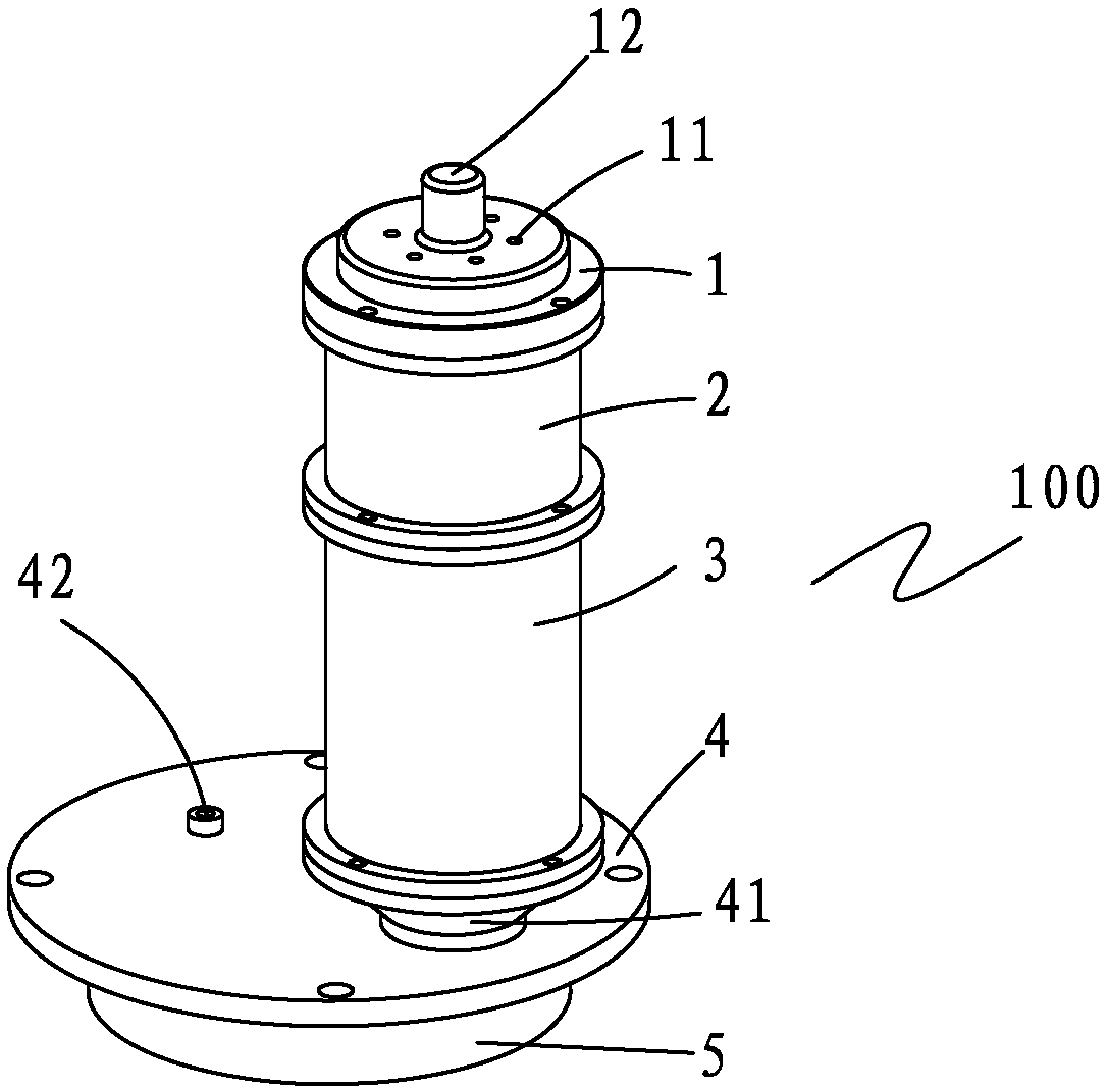
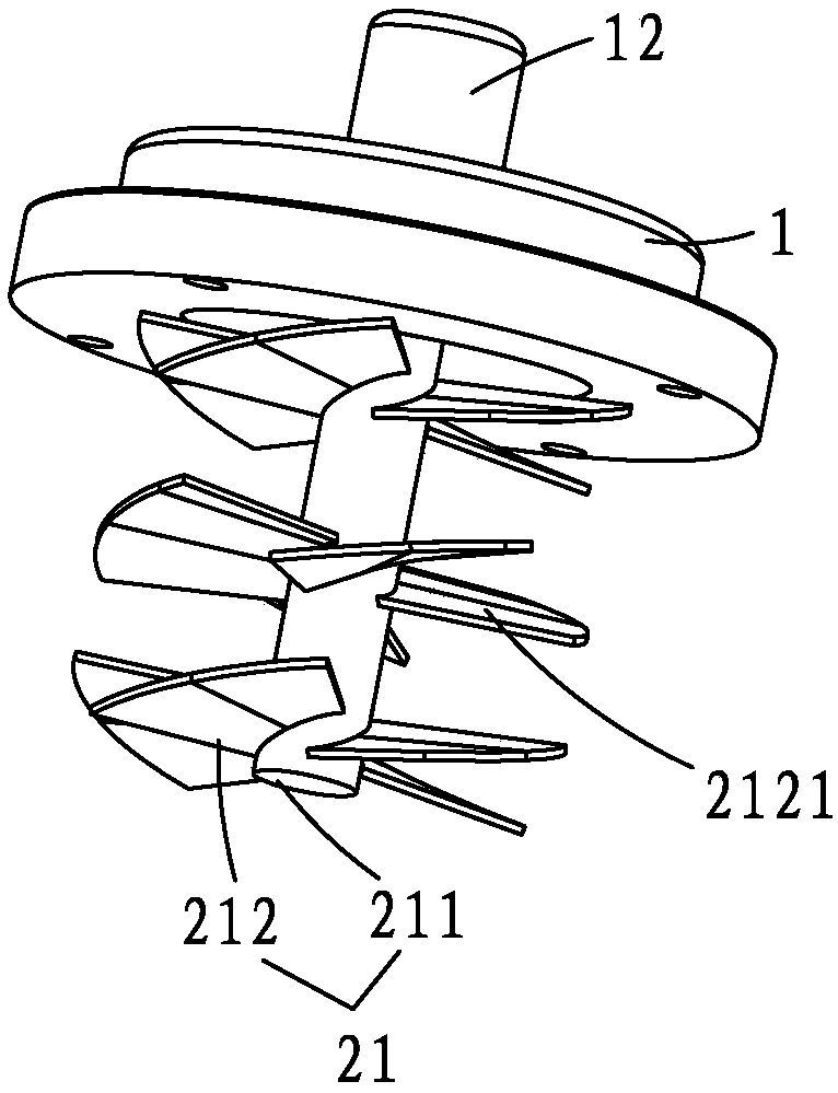
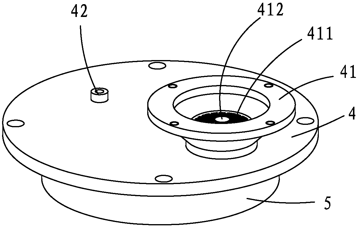
[0024] see Figure 1~4 , the present invention relates to a powder feeding device for laser cladding that can realize powder gradient changes. The powder feeding device 100 includes a top end cover 1, a powder mixing bin 2, a powder storage bin 3, a powder storage bin base 4 and a fixing seat 5, The top end cover 1 is arranged on the top of the powder mixing chamber 2, and a plurality of powder feeding holes 11 are provided on the top end cover 1, and a rotating powder mixing device 21 is arranged in the powder mixing chamber 2, and the rotating powder mixing device 21 is arranged in the powder mixing chamber 2. The device 21 is connected to the motor 12 through the top end cover 11, the motor 12 is arranged outside the top end cover 1, the powder storage bin 3 is connected to the other end of the powder mixing bin 2, and the powder storage bin base 4 is arranged below the powder storage bin 3 ;

[0025] The base of the powder storage bin 4 is connected and arranged above the...


PUM


Abstract

The invention provides a powder feeding device capable of realizing powder gradient change and for laser cladding. The powder feeding device comprises a top end cover, a powder mixing bin, a powder storage bin, a powder storage bin base and a fixing seat, wherein the top end cover is provided with a plurality of powder feeding holes and arranged at one end of the powder mixing bin, and a rotatingpowder mixing device is arranged in the powder mixing bin. The rotating powder mixing device is connected to a motor through the top end cover, and a first powder feeding portion and a first powder discharging hole are formed in the powder storage bin base. A first powder disk arranged on the fixing seat is connected to a second powder disk through a hollow tube, a second powder feeding hole formed in the first powder disk is connected to the first powder feeding portion, and a second powder discharging hole formed in the second powder disk is connected with the first powder discharging hole.The first powder feeding portion communicates with the bottom of the powder storage bin, a first screen is arranged at the bottom of the first powder feeding portion, and a micro oscillator is arranged on the first screen. The powder feeding device capable of realizing powder gradient change and for laser cladding can solves the problems that in existing powder feeding, clogging of a powder feeding pipe and a laser cladding head is prone to occurring, the powder utilization rate is low, and real-time gradient change of various kinds of powders cannot be realized in the cladding process.

Description

【Technical field】 [0001] The invention relates to a powder feeding device for laser cladding which can realize powder gradient change. 【Background technique】 [0002] Laser cladding technology belongs to a kind of surface modification technology. It is a rapid solidification process. By adding cladding materials on the surface of the substrate, the high energy density laser beam is used to rapidly melt alloys with different components and properties and the surface of the substrate. Synchronous powder feeding laser cladding technology has been developed rapidly, but the powder feeding device, as the core of synchronous powder feeding laser cladding technology, still has certain deficiencies. It is difficult to ensure the uniformity of the proportioned powder, and the production efficiency is reduced. At the same time, the cladding process cannot realize real-time gradient changes of various powders. [0003] The powder feeding device in the current market does not effective...

Claims


Application Information

Patent Timeline
Patent Type & Authority Applications(China)
IPC IPC(8): C23C24/10
CPCC23C24/10Y02P10/25
Inventor 练国富张浩姚明浦江吉彬
Owner FUJIAN UNIV OF TECH
Learn More