
Glass fiber compressing device with ejection structures

A glass fiber and jacking technology, which is applied in the field of glass fiber products, can solve the problems of single jacking structure and function, poor jacking effect, and increased difficulty of jacking, so as to avoid manual material transportation, facilitate input, and avoid temperature too high effect

Inactive Publication Date: 2018-11-06
JIANGSU SHENXIANG ELECTROMECHANICAL
View PDF0 Cites 0 Cited by
  • Summary
  • Abstract
  • Description
  • Claims
  • Application Information

AI Technical Summary

Problems solved by technology

[0004] The purpose of the present invention is to provide a glass fiber pressing device with a jacking structure, which solves the problem that the jacking structure in the existing glass fiber products has a single function, the effect of the jacking is poor, and it is necessary to carry out the process of pushing the material during the ejection process. Manual alignment increases the difficulty of jacking, and the general jacking structure only has the problem of pushing or pushing out one of the modes

Method used

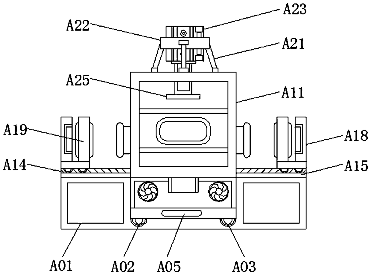
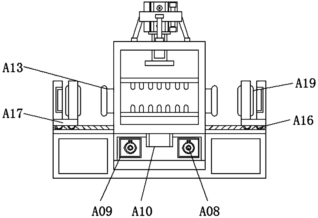
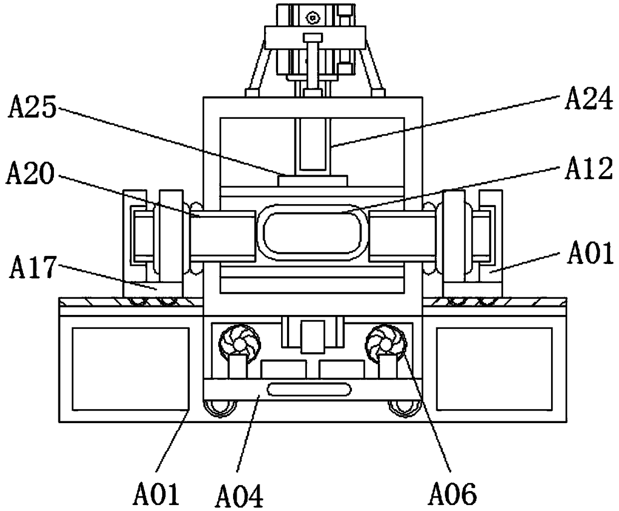

Image

  • Glass fiber compressing device with ejection structures
  • Glass fiber compressing device with ejection structures
  • Glass fiber compressing device with ejection structures

Examples


Embodiment Construction

[0023] The following will clearly and completely describe the technical solutions in the embodiments of the present invention with reference to the accompanying drawings in the embodiments of the present invention. Obviously, the described embodiments are only some, not all, embodiments of the present invention. Based on the embodiments of the present invention, all other embodiments obtained by persons of ordinary skill in the art without making creative efforts belong to the protection scope of the present invention.

[0024] see Figure 1-4 , a glass fiber pressing device with a top material structure, including a base A01, a storage box A04, a discharge port A10 and a bracket A21, the upper surface of the middle part of the base A01 is provided with a first slide rail A02, and the first slide rail The first pulley A03 is installed inside the A02, the shape of the base A01 is set as a "concave" structure, and the base A01 forms a sliding structure through the first slide ra...


PUM


Abstract

The invention discloses a glass fiber compressing device with ejection structures. The glass fiber compressing device comprises a base, a storage tank, a discharge outlet and a support. First slide rails are arranged on the upper surface of the middle of the base, first pulleys are mounted inside the first slide rails, a handle is mounted on a surface of the storage tank, the storage tank is positioned above the first pulleys, fans are mounted inside the storage tank, transmission shafts are connected with the rears of the fans, a mixing tank is arranged above the discharge outlet, a fixing platform is welded on the upper side of the support, and the support is positioned on the upper side of the mixing tank. The glass fiber compressing device has the advantages the ejection structures forglass fiber products have complete functions, good ejection effects can be realized, manual alignment can be omitted in procedures for pushing materials, and accordingly the ejection difficulty can be lowered; the ejection structures can be in a push-in mode and a push-out mode, the glass fiber compressing device is provided with the fans, the materials inside the storage tank can be cooled by the fans, and accordingly excessively high temperatures of processed materials can be prevented.

Description

technical field [0001] The invention relates to the technical field of glass fiber products, in particular to a glass fiber pressing device with a jacking structure. Background technique [0002] Glass fiber is an inorganic non-metallic material with excellent performance. There are many kinds. Its advantages are good insulation, strong heat resistance, good corrosion resistance and high mechanical strength. It is made of glass balls or waste glass through high-temperature melting, wire drawing, winding, weaving and other processes. The diameter of its single filament is several microns to more than 20 microns, which is equivalent to 1 of a hair. / 20-1 / 5, each bundle of fiber precursors is composed of hundreds or even thousands of monofilaments, glass fibers are usually used as reinforcing materials in composite materials, electrical insulation materials and thermal insulation materials, circuit substrates and other national economies In various fields, glass fiber products...

Claims


Application Information

Patent Timeline
IPC IPC(8): B29C70/40B29C70/54B29C35/16
CPCB29C70/40B29C35/16B29C70/541B29C2035/1658
Inventor 陈丁垚
Owner JIANGSU SHENXIANG ELECTROMECHANICAL
Learn More