Smashing device used for manufacturing renewable sponge

A pulverizing device and sponge technology, applied in the field of mechanical equipment, can solve the problems of aggravating environmental pollution, polluting the site environment, reducing production efficiency, etc., and achieving the effects of high efficiency, environmental protection and quality improvement

Inactive Publication Date: 2018-11-06
陈卫
View PDF5 Cites 3 Cited by
  • Summary
  • Abstract
  • Description
  • Claims
  • Application Information

AI Technical Summary

Problems solved by technology

[0002] Regenerated sponge is a new product. Although it is made by recycling industrial sponge waste, its use value is no less than that of sponge
In addition, the remaining sponge pieces and broken particles after industrial sponge cutting cannot be directly thrown to nature, and nature cannot naturally absorb these sponges. Even if it can be absorbed, it will take a long time; and if it is disposed of by burning Sponge waste, the toxic gas produced by burning, aggravates the pollution of the environment, so it is necessary to make the leftovers of industrial sponges into recycled sponges
The production of recycled sponges needs to crush the leftovers, and the existing crushing devices for making recycled sponges will generate a lot of dust when used, which not only pollutes the site environment, but also seriously affects the health of workers, and the untreated dust will fall again. into the sponge crushed particles, making the crushed particles full of dust and bacteria, reducing the quality of sponge crushed particles, reducing production efficiency, impractical and unreliable

Method used


Image

  • Smashing device used for manufacturing renewable sponge

Examples


Embodiment Construction

[0012] Below in conjunction with accompanying drawing and specific embodiment the present invention is described in further detail:

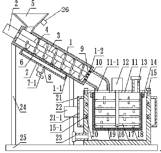
[0013] like figure 1 As shown, a crushing device for making regenerated sponges includes a bottom plate 25, a cylinder 1 is provided on the top surface of the bottom plate 25, and the cylinder 1 is inclined downward. A plurality of supporting cylinders 24, a motor A2 is fixed on the side of the cylinder 1, the driving end of the motor A2 extends into the cylinder 1, the driving end of the motor A2 is fixedly connected with a rotating shaft 3, and the rotating shaft 3 is fixed with a helical blade 4, the top surface of the cylinder 1 is fixed with a funnel 5, the bottom surface of the cylinder 1 is provided with a square through hole 1-1, and the square through hole 1-1 is fixed with a Filter screen 6, described square through-hole 1-1 external cover is provided with the cover body 7 that is fixed on cylinder body 1 bottom surface, and the botto...


PUM


Abstract

The invention discloses a smashing device used for manufacturing renewable sponge. The smashing device comprises a bottom plate. A cylinder body is arranged on the top face of the bottom plate and obliquely arranged downwards. Multiple supporting column bodies are fixed between the cylinder body and the bottom plate. A motor A is fixed to the side face of the cylinder body. The drive end of the motor A extends into the cylinder body. The drive end of the motor A is fixedly connected with a rotating shaft. Spiral blades are fixed to the side face of the rotating shaft. A funnel is fixed to thetop face of the cylinder body in a penetrating manner. The funnel is provided with a vibrating device. A square through hole is formed in the bottom face of the cylinder body. A filter screen is arranged in the square through hole. A cover body fixed to the bottom face of the cylinder body covers the exterior of the square through hole. A wind sucking opening is arranged in the bottom face of thecover body. A dust collector communicating with the wind sucking opening is fixed to the bottom face of the cover body. A through hole is formed in the other side of the cylinder body. According to the smashing device, the cylinder body arranged obliquely and the dust collector are designed, dust in smashed particles of the sponge can be effectively cleared, cleaning liquid is used for washing andremoving bacteria in the box body, the environment of the work site is protected, the quality of the smashed particles of the sponge is improved, and the smashing device is high in efficiency, practical and reliable.

Description

technical field [0001] The invention relates to the field of mechanical equipment, in particular to a crushing device for making regenerated sponges. Background technique [0002] Regenerated sponge is a new type of product. Although it is made by recycling industrial sponge waste, its use value is no less than that of sponge. In addition, the remaining sponge pieces and broken particles after industrial sponge cutting cannot be directly thrown to nature, and nature cannot naturally absorb these sponges. Even if it can be absorbed, it will take a long time; and if it is disposed of by burning Sponge waste, the toxic gas produced by burning, aggravates the pollution of the environment, so it is necessary to make the leftovers of industrial sponges into recycled sponges. The production of recycled sponges needs to crush the leftovers, and the existing crushing devices for making recycled sponges will generate a lot of dust when used, which not only pollutes the site environme...

Claims


Application Information

Patent Timeline
IPC IPC(8): B29B17/00B29B17/04B08B15/04B08B3/10B08B3/04F26B21/00
CPCB08B3/047B08B3/10B08B15/04B29B17/00B29B17/0412B29B2017/044F26B21/004Y02W30/62
Inventor 陈卫
Owner 陈卫
Why Eureka
Try Eureka