
High-precision numerical control machining tool

A CNC machine tool, high-precision technology, applied in metal processing mechanical parts, metal processing equipment, manufacturing tools, etc., can solve the problems of inability to measure height, extrusion workpiece damage, CNC machining errors, etc., to increase precision, operation Convenience and simple structure

Inactive Publication Date: 2018-11-06
南京万卓机电有限公司
View PDF0 Cites 2 Cited by
  • Summary
  • Abstract
  • Description
  • Claims
  • Application Information

AI Technical Summary

Problems solved by technology

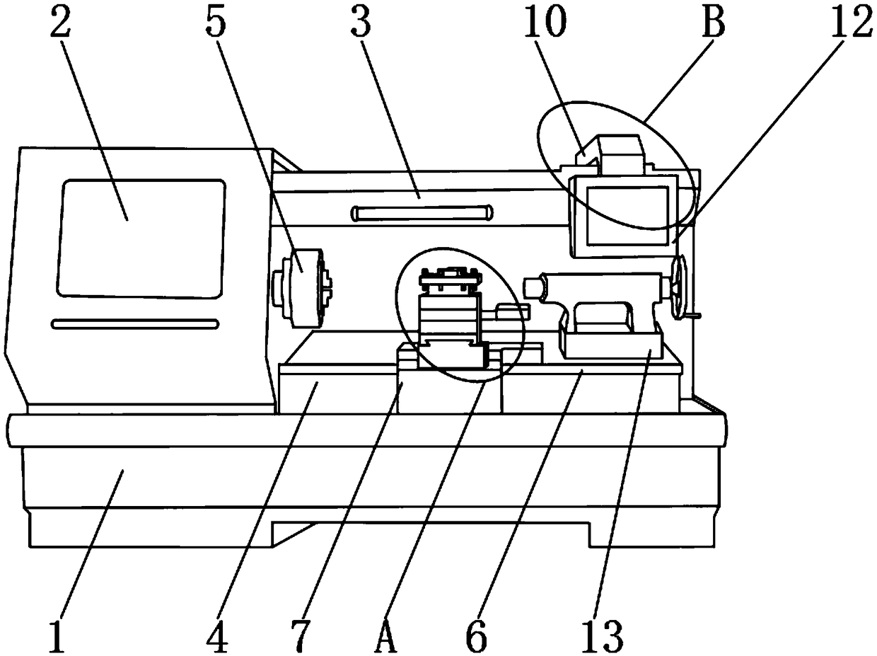
[0002] CNC machining machine tool is one of the most widely used CNC machine tools at present. It is mainly used for cutting processing of inner and outer cylindrical surfaces of shaft parts or disk parts, inner and outer conical surfaces of arbitrary cone angles, complex rotary inner and outer curved surfaces, and cylindrical and conical threads. , and can perform grooving, drilling, reaming, reaming and boring, etc., the existing CNC machine tools cannot meet the needs of people; the existing CNC machine tools have certain disadvantages when they are in use. First of all, they cannot control The telescopic control of the panel makes it impossible to adjust the distance between the control panel and the shell, which is not convenient for the use of the control panel. Secondly, it is not possible to perform protective clamping on the workpiece to be processed, which is easy to cause damage due to extrusion of the workpiece during the clamping process. Finally, it is not possible to It can measure the height of the tool clamping process, but it is impossible to measure the clamping height conveniently. CNC machining is easy to cause errors, which has a certain impact on people's use process. Therefore, we propose a high-precision CNC machining machine tool

Method used


Image

  • High-precision numerical control machining tool
  • High-precision numerical control machining tool
  • High-precision numerical control machining tool

Examples


Embodiment Construction

[0017] In order to make the technical means, creative features, goals and effects achieved by the present invention easy to understand, the present invention will be further described below in conjunction with specific embodiments.

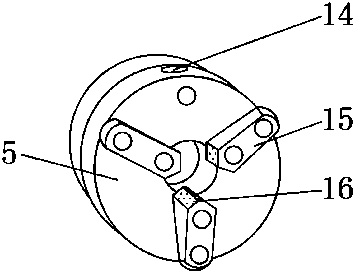
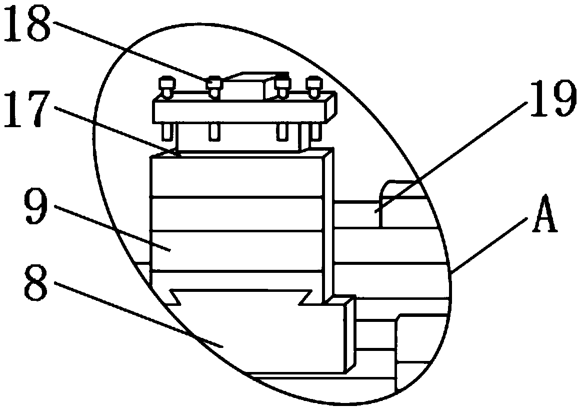
[0018] Such as Figure 1-4 As shown, a high-precision numerical control processing machine tool includes a machine tool base 1, a spindle box 2 and a machine tool shell 3, the spindle box 2 is located at the upper end of the machine tool base 1, the machine tool shell 3 is located at the rear side of the upper end of the machine tool base 1, and the machine tool base 1 A worktable 4 is fixedly installed on the other side of the upper end, a three-jaw chuck 5 is installed on one side of the upper end of the headstock 2, a Z-direction slide rail 6 is fixedly installed on the upper end of the worktable 4, and a Z-direction slide rail 6 is installed on the upper end of the Z-direction slide rail 6. Slider 7, the upper end of the Z-direction slider 7 i...


PUM


Abstract

The invention discloses a high-precision numerical control machining tool comprising a tool base, a spindle box and a tool shell. The spindle box is located at the upper end of the tool base. The toolshell is located on the rear side of the upper end of the tool base. A workbench is fixedly installed on the other side of the upper end of the tool base. A three-jaw chuck is arranged on one side ofthe upper end of the spindle box. A Z-direction sliding rail is fixedly installed at the upper end of the workbench. The high-precision numerical control machining tool is provided with a telescopicrod, a buffer gasket and an altimeter, a control panel can be controlled telescopically, the distance from the control panel to the shell can be adjusted conveniently, the control panel can be used conveniently, a to-be-machined workpiece can be clamped in a protective mode, harm caused by workpiece extrusion in the clamping process is avoided, height measurement can be conducted on the clamping process of a cutter, the standard clamping height is met, numerical control machining precision is improved, certain practicability is achieved, and better use prospects are brought.

Description

technical field [0001] The invention relates to the field of numerically controlled processing machine tools, in particular to a high-precision numerically controlled processing machine tool. Background technique [0002] CNC machining machine tool is one of the most widely used CNC machine tools at present. It is mainly used for cutting processing of inner and outer cylindrical surfaces of shaft parts or disk parts, inner and outer conical surfaces of arbitrary cone angles, complex rotary inner and outer curved surfaces, and cylindrical and conical threads. , and can perform grooving, drilling, reaming, reaming and boring, etc., the existing CNC machine tools cannot meet the needs of people; the existing CNC machine tools have certain disadvantages when they are in use. First of all, they cannot control The telescopic control of the panel makes it impossible to adjust the distance between the control panel and the shell, which is not convenient for the use of the control pa...

Claims


Application Information

Patent Timeline
IPC IPC(8): B23Q1/72B23Q3/10B23Q17/22
CPCB23Q1/72B23Q3/10B23Q17/22
Inventor 陆福萍
Owner 南京万卓机电有限公司
Learn More