Waste gas treatment device for chemical reaction kettle

A waste gas treatment device and chemical reaction technology, applied in the direction of feeding devices, chemical/physical processes, chemical instruments and methods, etc., can solve problems such as hazards, environmental hazards, waste gas classification collection and treatment, etc., to achieve broad market prospects, Huge economic benefits, novel design effect

Inactive Publication Date: 2018-11-06
GUILIN SHIHUAN WASTE GAS TREATMENT EQUIP
View PDF0 Cites 6 Cited by
  • Summary
  • Abstract
  • Description
  • Claims
  • Application Information

AI Technical Summary

Problems solved by technology

[0002] The broad understanding of the reactor is a container with physical or chemical reactions. Through the structural design and parameter configuration of the container, the heating, evaporation, cooling and low-speed mixing functions required by the process are realized. The application of the reactor has played an important role in the chemical industry. It plays a very important role and brings great convenience, but with the use of the reactor, some small problems have gradually emerged. For example, some reactors will directly discharge the treated waste gas into the air during use. , which has caused harm to the environment and our health. Although some reactors also have treatment for exhaust gas, the gas in the reactor cannot be completely discharged, resulting in incomplete treatment and inability to treat exhaust gas well. Classified collection and treatment, therefore, there is an increasing demand for a waste gas treatment device for chemical reactors
[0003] Some reactors currently on the market will discharge the treated waste gas directly into the air during use. This method is extremely harmful to our living environment. The gas in the kettle cannot be completely discharged, resulting in incomplete treatment, and the waste gas cannot be collected and processed in a good way. Therefore, a waste gas treatment device for chemical reaction kettles is proposed to solve the above problems.

Method used


Image

  • Waste gas treatment device for chemical reaction kettle
  • Waste gas treatment device for chemical reaction kettle

Examples


Embodiment Construction

[0017] The following will clearly and completely describe the technical solutions in the embodiments of the present invention with reference to the accompanying drawings in the embodiments of the present invention. Obviously, the described embodiments are only some, not all, embodiments of the present invention. Based on the embodiments of the present invention, all other embodiments obtained by persons of ordinary skill in the art without making creative efforts belong to the protection scope of the present invention.

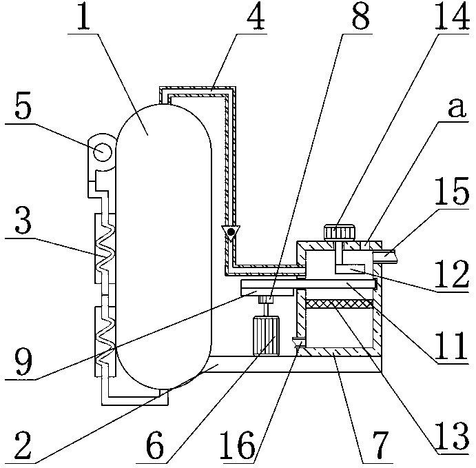
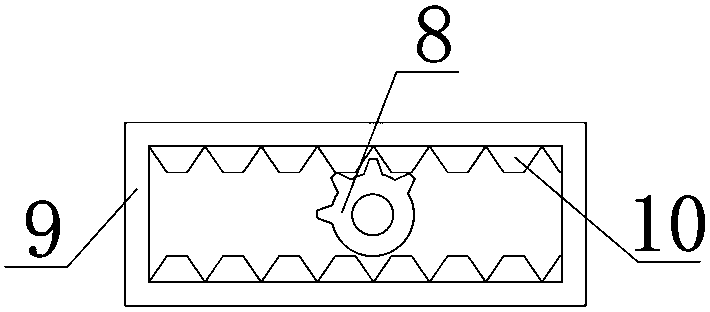
[0018] see Figure 1-2 , the present invention provides a technical solution:

[0019] An exhaust gas treatment device for a chemical reaction kettle, comprising a reaction kettle 1, a base 2 is fixedly connected to the bottom end of the right end surface of the reaction kettle 1, and a condenser pipe 3 is connected to the air inlet of the bottom end surface of the reaction kettle 1, and the reaction kettle 1 The air outlet on the top surface is connected wit...


PUM


Abstract

The invention relates to the technical field of waste gas treatment and in particular relates to a waste gas treatment device for a chemical reaction kettle. The waste gas treatment device comprises areaction kettle, wherein the bottom end of the right end face of the reaction kettle is fixedly connected with a base; an air inlet in the bottom end face of the reaction kettle is communicated witha condenser pipe; an air outlet in the top end face of the reaction kettle is communicated with an air outlet pipe; an air blower is fixedly connected to the left end face of the reaction kettle and communicated with the condenser pipe; a first motor and a treatment box arranged on the left and right sides are fixedly connected to the top end face of the base; the other end of the air outlet pipeis communicated with the treatment box; the tail end of the spindle of the first motor is fixedly connected with a gear; a fixing rack is arranged at the top end of the first motor; and a rack is arranged on the inner side of the fixing rack. According to the waste gas treatment device disclosed by the invention, due to the arrangement of the condenser pipe, gases blown out by the air blower are cooled, and the temperature difference between gases in the reaction kettle and the gases blown in is increased, so that the waste gases in the reaction kettle are compressed out and the waste gases inthe reaction kettle can be discharged to the greatest degree.

Description

technical field [0001] The invention relates to the technical field of waste gas treatment, in particular to a waste gas treatment device for a chemical reaction kettle. Background technique [0002] The broad understanding of the reactor is a container with physical or chemical reactions. Through the structural design and parameter configuration of the container, the heating, evaporation, cooling and low-speed mixing functions required by the process are realized. The application of the reactor has played an important role in the chemical industry. It plays a very important role and brings great convenience, but with the use of the reactor, some small problems have gradually emerged. For example, some reactors will directly discharge the treated waste gas into the air during use. , which has caused harm to the environment and our health. Although some reactors also have treatment for exhaust gas, the gas in the reactor cannot be completely discharged, resulting in incomplet...

Claims


Application Information

Patent Timeline
Patent Type & Authority Applications(China)
IPC IPC(8): B01D53/78B01D53/64B01J4/00B01D35/02B01D29/03
CPCB01D53/78B01D29/03B01D35/02B01D53/64B01J4/001
Inventor 钟万平
Owner GUILIN SHIHUAN WASTE GAS TREATMENT EQUIP
Why Eureka
Try Eureka