Drive circuit

A driving circuit and integrated driving technology, applied in the direction of logic circuits, electrical components, reliability improvement and modification, etc., can solve the problems of burning and high temperature of electrical components, and achieve the effect of preventing over-temperature or even burning

Active Publication Date: 2018-11-02
QISDA OPTRONICS (SUZHOU) CO LTD +1
View PDF5 Cites 2 Cited by
  • Summary
  • Abstract
  • Description
  • Claims
  • Application Information

AI Technical Summary

Problems solved by technology

[0003] The purpose of the present invention is to provide a driving circuit to solve the problem in the prior art that the current flowing through the power-consuming element in the standby mode is the same as that in the normal working mode, which causes the power-consuming element to be overheated or even burned in the standby mode. question

Method used


Image

  • Drive circuit
  • Drive circuit
  • Drive circuit

Examples


Embodiment Construction

[0026] The following descriptions of the various embodiments refer to the accompanying drawings to illustrate specific embodiments in which the present invention can be practiced. The directional terms mentioned in the present invention, such as "upper", "lower", "front", "rear", "left", "right", "side", etc., are only referring to the directions of the attached drawings. Therefore, the directional terms used are used to illustrate and understand the present invention, but not to limit the present invention.

[0027] In the following embodiments, the same parts are denoted by the same symbols in different drawings.

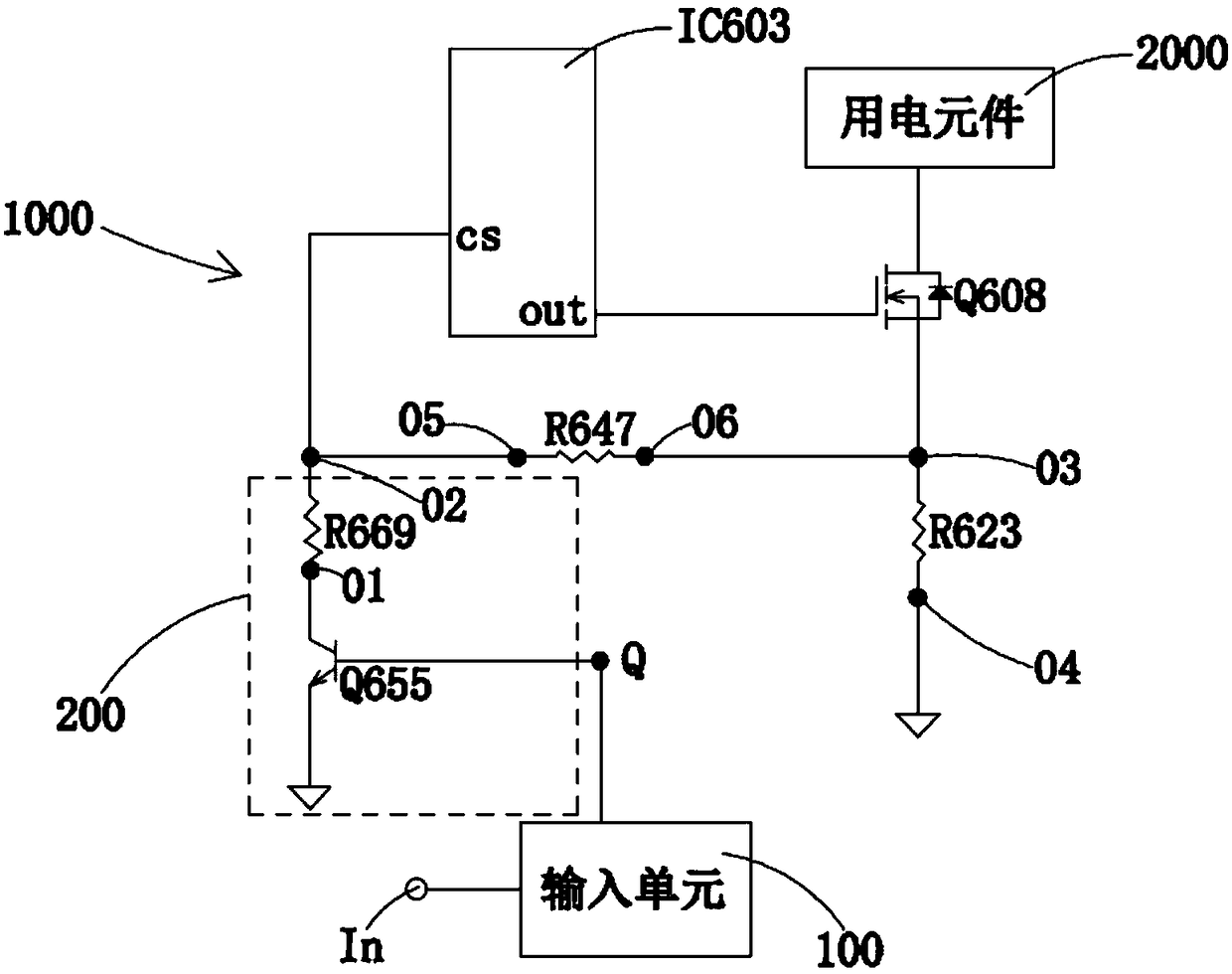
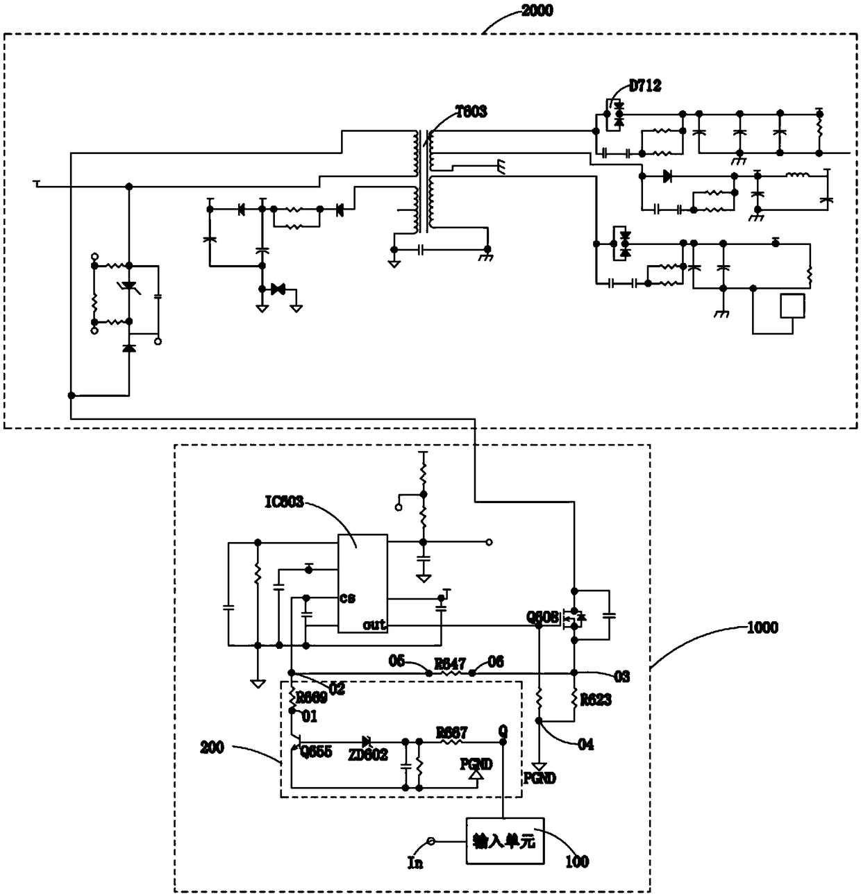
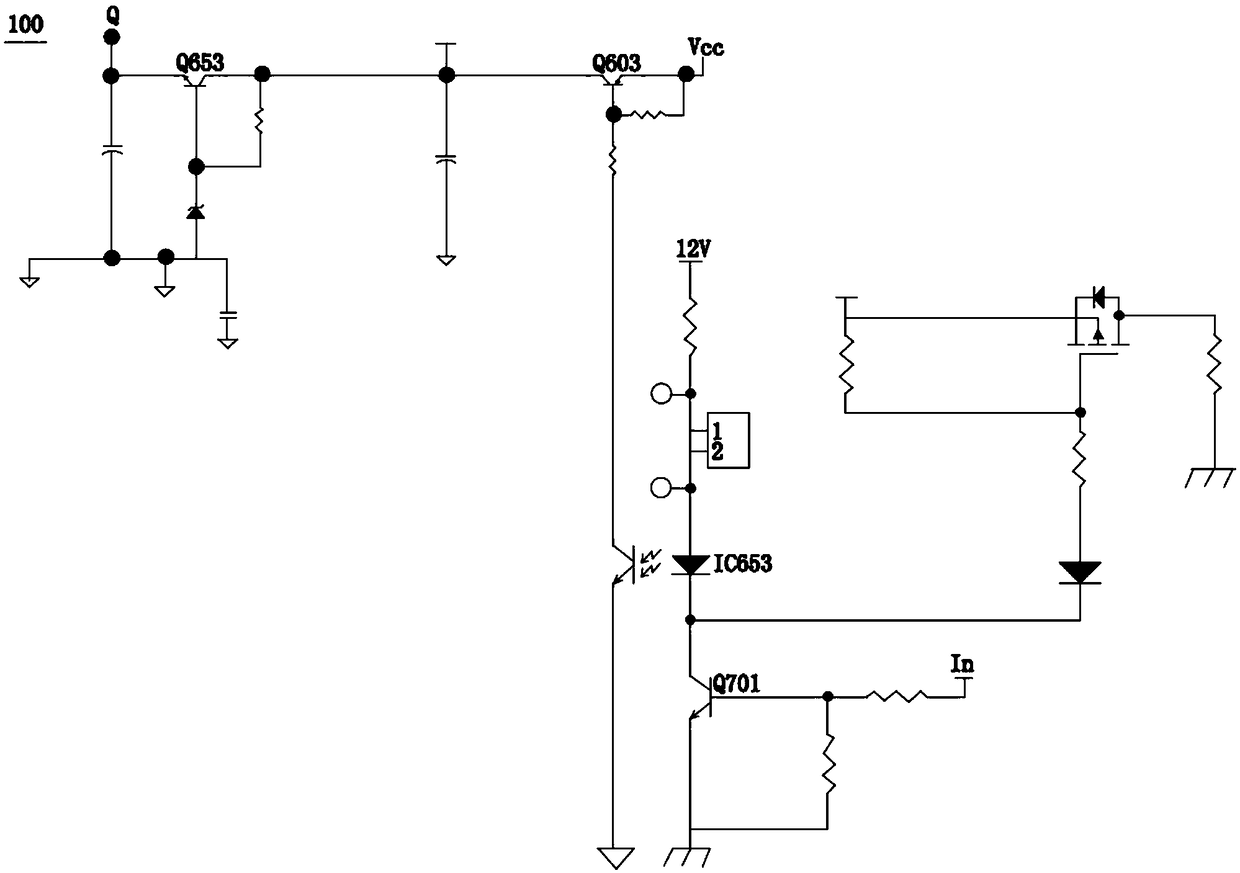
[0028] Please refer to figure 1 , figure 1 It is a schematic diagram of the driving circuit of the present invention. The driving circuit 1000 of the present invention is used to drive the electric element 2000 . The driving circuit 1000 includes an input unit 100 , an integrated driving chip IC603 , a switching unit 200 , a monitoring resistor R623 and a seco...


PUM


Abstract

The invention discloses a drive circuit for driving an electric element. The drive circuit comprises an input unit with an input end and a first node; an integrated drive chip with an over power protection port; a switching unit with a first resistor and a first switch; a monitoring resistor; and a second resistor. When a first signal is a first high level signal, the first resistor is switched on. Two ends of the first resistor are equipped with first voltages. A voltage of the over power protection port is the first voltage. When the first signal is a first low level signal, the first resistor is not switched on. Two ends of the monitoring resistor are equipped with second monitoring voltages. The voltage of the over power protection port is the second monitoring voltage. According to the drive circuit, through setting of the switching unit, when the drive circuit is in a standby mode, a current flowing into the electric element is relatively low, so a phenomenon that the electric element is overtemperature or even is burnt due to inflow of a heavy current is prevented.

Description

technical field [0001] The invention relates to a driving circuit, in particular to a driving circuit capable of preventing overheating of electrical components in a standby mode. Background technique [0002] In the current projector, in the standby mode, its over power protection (over power protection, OPP) operating point is almost the same as that in the normal working mode. Since the cooling fan in the projector does not rotate in the standby mode, and the drive circuit is the same as that in the normal working mode, the current flowing through the electrical components (such as transformers, etc.) is the same as in the normal working mode. The fan does not rotate, which will cause the temperature of the electrical components to be too high or even burnt in the standby mode. Contents of the invention [0003] The purpose of the present invention is to provide a driving circuit to solve the problem in the prior art that the current flowing through the power-consuming...

Claims


Application Information

Patent Timeline
Patent Type & Authority Applications(China)
IPC IPC(8): H03K19/003H03K19/018
CPCH03K19/00376H03K19/01825
Inventor 陈启仁林俊孝杜圣旗
Owner QISDA OPTRONICS (SUZHOU) CO LTD
Why Eureka
Try Eureka