
A method for detecting rotor position of permanent magnet spherical motor based on optical sensor

A rotor position detection and optical sensor technology, applied in the direction of using optical devices, electromechanical devices, instruments, etc., to achieve the effect of reducing errors, light material, and small errors

Active Publication Date: 2020-07-28
ANHUI UNIVERSITY
View PDF5 Cites 0 Cited by
  • Summary
  • Abstract
  • Description
  • Claims
  • Application Information

AI Technical Summary

Problems solved by technology

To realize the closed-loop control of spherical motors, position detection is a key link, but so far, there is no feasible position detection scheme that can meet the needs of closed-loop control of spherical motors

Method used


Image

  • A method for detecting rotor position of permanent magnet spherical motor based on optical sensor
  • A method for detecting rotor position of permanent magnet spherical motor based on optical sensor
  • A method for detecting rotor position of permanent magnet spherical motor based on optical sensor

Examples


Embodiment Construction

[0032] In order to make the object, technical solution and advantages of the present invention clearer, the present invention will be further described in detail below in conjunction with the accompanying drawings and embodiments. It should be understood that the specific embodiments described here are only used to explain the present invention, not to limit the present invention. In addition, the technical features involved in the various embodiments of the present invention described below can be combined with each other as long as they do not constitute a conflict with each other.

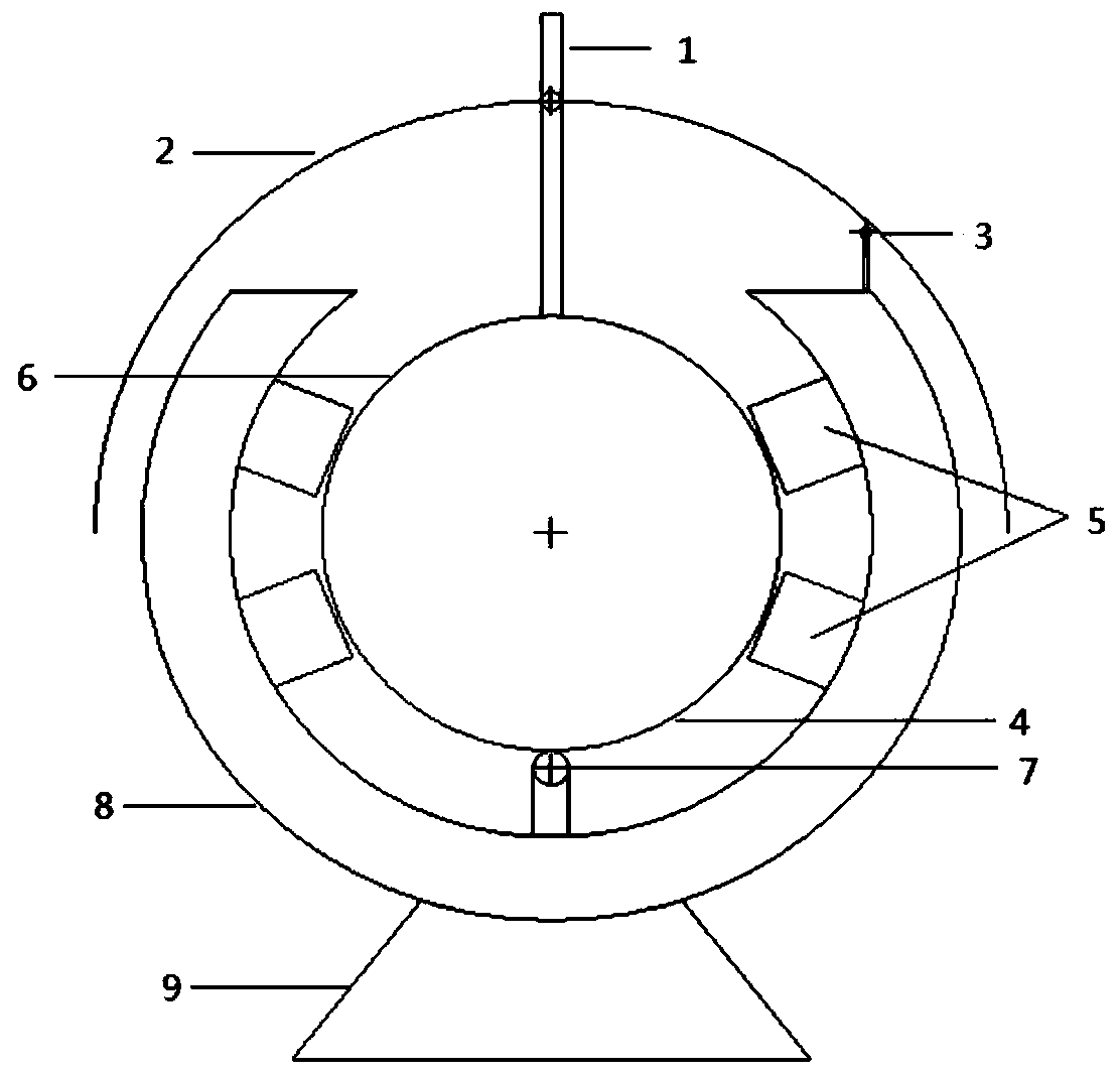
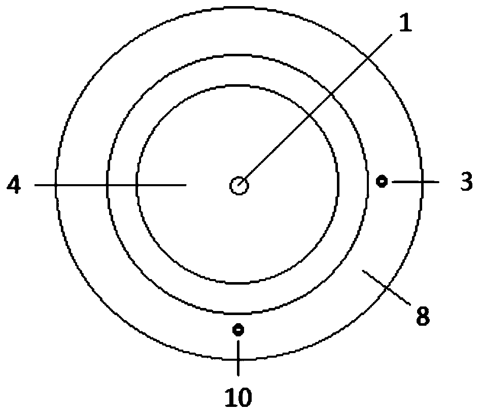
[0033] The invention provides a method for detecting the rotor position of a permanent magnet spherical motor based on an optical sensor, see Figure 1a , Figure 1b The permanent magnet spherical motor of the present invention comprises a motor base 9, a spherical motor stator housing 8, a universal joint 7, a stator coil 5 distributed in two layers on the spherical motor stator housing 8, and ...


PUM


Abstract

The invention discloses a method for detecting the rotor position of a permanent magnet spherical motor based on an optical sensor, comprising a permanent magnet spherical motor, a hemispherical casing, a hardware detection circuit based on an optical sensor, an ARM development board and a position calculation algorithm, and is characterized in that : The hemispherical casing is fixed on the output shaft of the spherical motor rotor, and two optical sensors are fixedly placed on the spherical motor stator casing at an interval of 90°; the displacement information of the moving hemispherical casing surface is obtained by detection of the two optical sensors , by calculating the position of the displacement information, the yaw angle and pitch angle of the hemispherical casing motion can be obtained, and the position coordinates of point P on the hemispherical casing can be obtained by solving, because the spherical rotor and the hemispherical casing are coaxial and concentric And according to the relationship between the two radii, the position coordinates of point S on the spherical rotor can be obtained. The hardware structure based on the method of the invention is relatively simple, the location coordinate solution algorithm is easy to realize, the detection error is small, and the method has strong practical application value.

Description

technical field [0001] The invention belongs to the technical field of detecting the rotor position of a permanent magnet spherical motor, and more specifically relates to a method for detecting the rotor position of a permanent magnet spherical motor based on an optical sensor. Background technique [0002] With the advancement of science and technology, industrial devices have embarked on the road of diversification, automation and intelligence. In actual industrial applications, they are inseparable from ships, automobiles, industrial robots and manipulators, as small as household appliances and smart devices. motor. With the improvement of application requirements, the requirements for motor function and performance are also relatively increased. Some special structural devices that perform complex movements, such as industrial robots, often need to complete multi-dimensional motion control in space. If a traditional single-degree-of-freedom industrial motor is used, th...

Claims


Application Information

Patent Timeline
Patent Type & Authority Patents(China)
IPC IPC(8): H02K11/22G01B11/00
CPCG01B11/002H02K11/22
Inventor 过希文李建王群京李绅文彦宫能伟程高梅
Owner ANHUI UNIVERSITY
Learn More