Vision-based dynamic target tracking and positioning method for unmanned aerial vehicle

A technology of dynamic target and positioning method, which is applied in measurement devices, instruments, optical devices, etc., to achieve the effect of improving the level of intelligence

Inactive Publication Date: 2018-11-02
中交遥感载荷(江苏)科技有限公司
View PDF1 Cites 23 Cited by
  • Summary
  • Abstract
  • Description
  • Claims
  • Application Information

AI Technical Summary

Problems solved by technology

And the guidance of UAVs is angle guidance in most cases, not position guidance, so there are certain limitations

Method used


Image

  • Vision-based dynamic target tracking and positioning method for unmanned aerial vehicle
  • Vision-based dynamic target tracking and positioning method for unmanned aerial vehicle
  • Vision-based dynamic target tracking and positioning method for unmanned aerial vehicle

Examples


Embodiment Construction

[0040] Now in conjunction with accompanying drawing, invention is described in further detail. These drawings are all simplified schematic diagrams, which only illustrate the basic structure of the invention in a schematic way, so they only show the composition related to the invention.

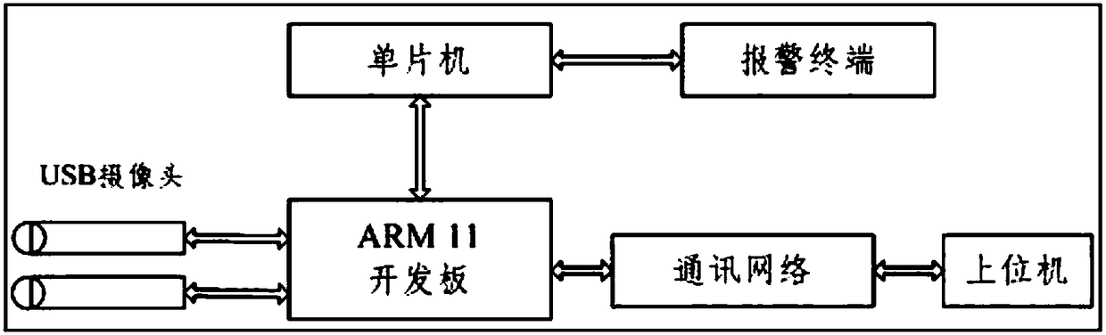
[0041] As shown in the figure, the general principle of the present invention is schematically shown as figure 1As shown, the binocular image information is collected through the left and right cameras of the USB interface, and the image is processed by the ARM11 development board to capture the position and geometric size information of the target object, which provides the basis for automatic early warning and corresponding measures for the background staff.

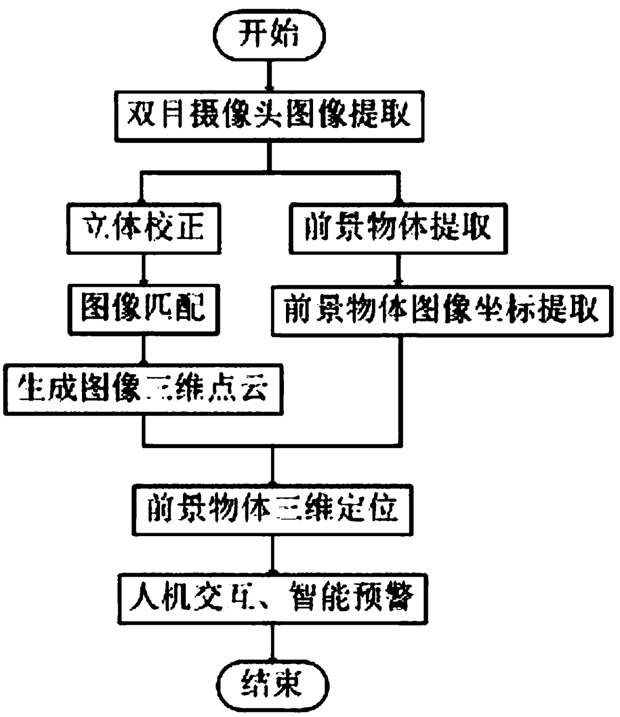
[0042] In the present invention, the target object measurement and positioning process is as follows: figure 2 As shown, the binocular image information is collected through the left and right cameras, and the 16 x 12 chessboard is ...


PUM


Abstract

The invention relates to a vision-based dynamic target tracking and positioning method for an unmanned aerial vehicle. According to the method, two cameras are utilized to collect the image of a monitoring area; by means of background dynamic update and target object extraction of the monitoring area, the three-dimensional point cloud of a visual angle area is generated through using a binocular recognition and positioning principle; and a target object is dynamically tracked on the basis of the target object extraction and the binocular recognition and positioning principle. According to thevision-based dynamic target tracking and positioning method for the unmanned aerial vehicle of the invention, visual ranging and target tracking are combined in the video monitoring field; the pixel coordinates of an image where the target is located are determined through target dynamic tracking; the three-dimensional point cloud is generated on the basis of the visual ranging; the target objectis locked, and the three-dimensional coordinates of the target object are determined; when the target object enters a warning area, a system can issue an alarm to achieve a real-time warning function;the captured position information of the target object provides a scientific basis for the actual operation of background staff.

Description

technical field [0001] The invention relates to unmanned aerial vehicle vision control technology, in particular to a vision-based dynamic target tracking and positioning method for unmanned aerial vehicles. Background technique [0002] UAVs usually perceive the surrounding environment through visual sensors, and the ground station processes and analyzes the downlinked sensor information to obtain effective information to guide the UAV to fly. The optoelectronic equipment often carried by drones includes CCD photoelectric cameras, infrared thermal imaging cameras, and synthetic aperture radar imaging. Among them, the CCD camera can not only obtain high-resolution image intelligence, but also easily combine with the infrared focal plane array to form a multi-spectral imaging system, so it becomes the first choice or even the only photoelectric vision sensor for small UAVs. [0003] The UAV uses the onboard CCD camera to monitor the flight area. The acquired aerial image is ...

Claims


Application Information

Patent Timeline
Patent Type & Authority Applications(China)
IPC IPC(8): G01B11/00
Inventor 高扬赵钧徐玉良闫廷廷
Owner 中交遥感载荷(江苏)科技有限公司
Why Eureka
Try Eureka