Combined force-bearing device for high-rise building or bridge tower construction

A high-rise building and combined technology, applied to the preparation of building components on site, construction, building construction, etc., can solve the problems of complex formwork design, poor forming surface accuracy, and small bearing capacity of a single fulcrum, so as to improve construction efficiency , few repair points, large bearing capacity

Active Publication Date: 2018-11-02
CHINA CONSTR THIRD ENG BUREAU GRP CO LTD
View PDF14 Cites 1 Cited by
  • Summary
  • Abstract
  • Description
  • Claims
  • Application Information

AI Technical Summary

Problems solved by technology

[0002] In the construction of bridge towers, the surface lines of the bridge towers are characterized by many changes. If the traditional formwork system for bridge tower construction is adopted, because most of the formwork fulcrums are arranged in the middle of the wall, the bearing capacity of a single fulcrum is small, the design of the formwork is complicated, and the on-site It is difficult to disassemble and modify, and for the curved surface of the corner of the tower column, the construction of the conventional formwork is difficult, and the precision of the forming surface is poor

Method used


Image

  • Combined force-bearing device for high-rise building or bridge tower construction
  • Combined force-bearing device for high-rise building or bridge tower construction
  • Combined force-bearing device for high-rise building or bridge tower construction

Examples


Embodiment Construction

[0024] In order to make the object, technical solution and advantages of the present invention clearer, the present invention will be further described in detail below in conjunction with the accompanying drawings and embodiments. It should be understood that the specific embodiments described here are only used to explain the present invention, not to limit the present invention.

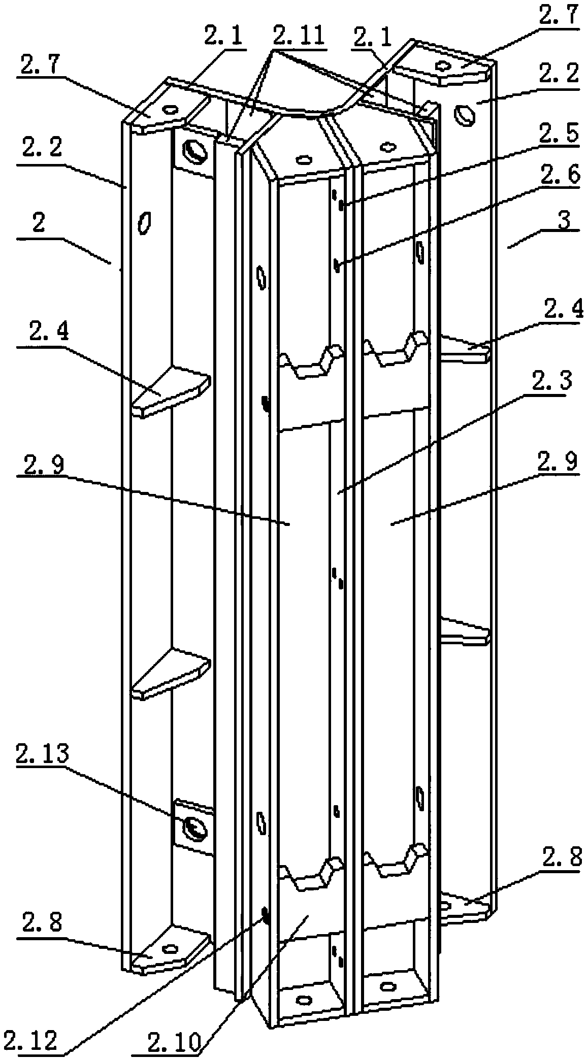
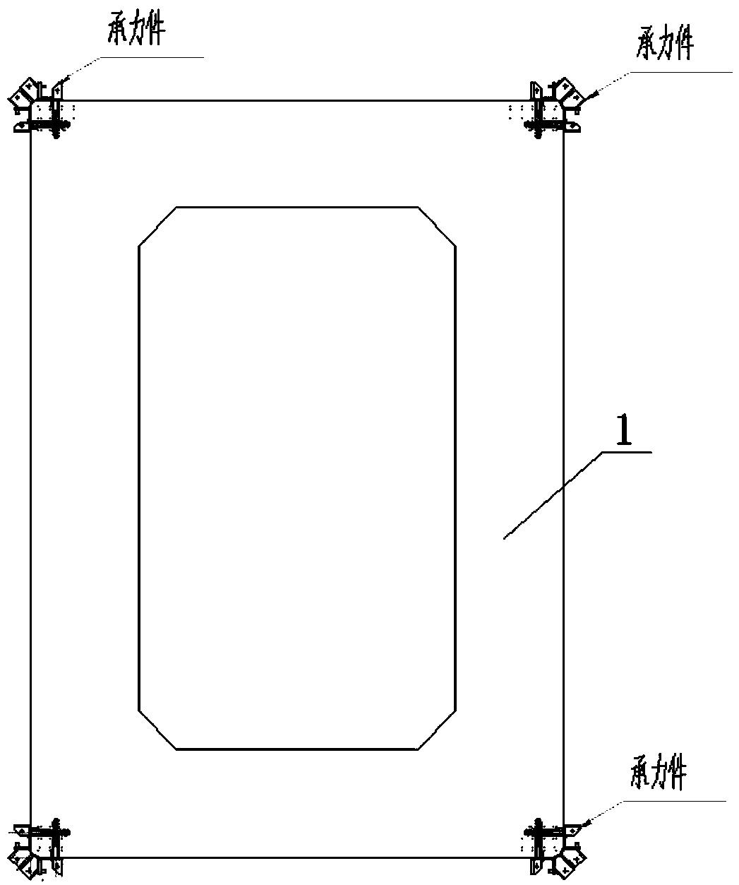
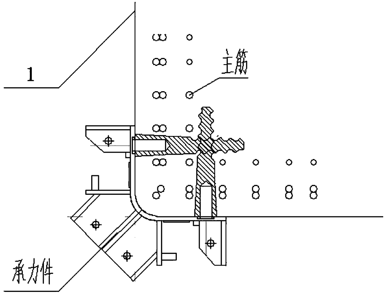
[0025] like Figure 1-Figure 3 As shown, a combined load-bearing device for high-rise buildings or bridge tower construction is installed at the corner of high-rise buildings or bridge towers (tower column 1), the device includes a first load-bearing member 2 and a second load-bearing Part 3, the structure of the two load-bearing parts is roughly the same, both including the load-bearing plate 2.1, the first side plate 2.2 and the second side plate 2.3, the force-bearing plate 2.1 is installed on the wall, and the first side plate 2.2 is vertically installed on the One side of the load-bearing pla...


PUM


Abstract

The invention discloses a combined force-bearing device for high-rise building or bridge tower construction. The combined force-bearing device is mounted at a corner of a high-rise building or bridgetower and comprises a first force-bearing part and a second force-bearing part. Each of the two force-bearing parts comprises a force-bearing plate, a first side plate and a second side plate, whereinthe force-bearing plate is mounted on a wall, the first side plate is vertically mounted on one side of the force-bearing plate and connected with a large mould plate, and the second side plate is vertically mounted on the other side of the force-bearing plate. The two force-bearing parts form a corner mould identical to the corner in shape through connection of the second side plates. Supportingpoints avoid decorative moulding and prestress positions and are close to tower column corners, high bearing capacity of single supporting points, low quantity of the supporting points and low quantity of construction face embedded bolt repair points are realized, and construction efficiency can be greatly improved.

Description

technical field [0001] The invention belongs to the technical field of building construction, and relates to a formwork system used for the construction of super high-rise buildings and super high bridge towers, in particular to a combined load-bearing device with the functions of corner forms and rails. Background technique [0002] In the construction of bridge towers, the surface lines of the bridge towers are characterized by many changes. If the traditional formwork system for bridge tower construction is adopted, because most of the formwork fulcrums are arranged in the middle of the wall, the bearing capacity of a single fulcrum is small, the design of the formwork is complicated, and the on-site It is difficult to disassemble and modify, and for the curved surface of the corner of the tower column, the construction of the conventional formwork is difficult, and the precision of the forming surface is poor. Contents of the invention [0003] The purpose of the prese...

Claims


Application Information

Patent Timeline
Patent Type & Authority Applications(China)
IPC IPC(8): E04G13/00E01D21/00
CPCE01D21/00E04G13/00
Inventor 王辉王开强陈波刘晓升朱磊磊周勇曹振杰杨辉
Owner CHINA CONSTR THIRD ENG BUREAU GRP CO LTD
Why Eureka
Try Eureka