Mounting device for a print head

A technology for installing equipment and printing heads, which is applied in printing, printing devices, inking devices, etc., and can solve the problems that fine mechanical solutions are easily polluted

Active Publication Date: 2018-11-02
HEIDELBERGER DRUCKMASCHINEN AG
View PDF13 Cites 0 Cited by
  • Summary
  • Abstract
  • Description
  • Claims
  • Application Information

AI Technical Summary

Problems solved by technology

This calibration can only be performed by professionals
It is also disadvantageous that these delicate mechanical solutions in the state of the art are easily contaminated (e.g. by inks)

Method used


Image

  • Mounting device for a print head
  • Mounting device for a print head
  • Mounting device for a print head

Examples


Embodiment Construction

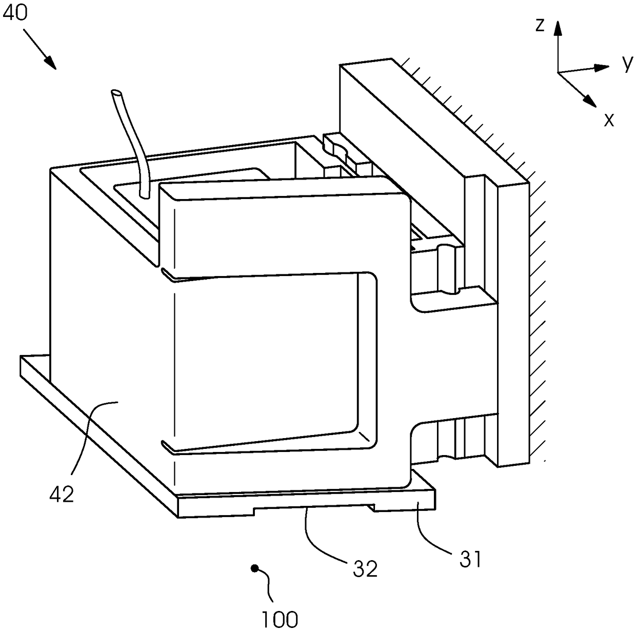
[0029] figure 1 The spatial view of is given an overview of the mounting device 40 and its structure. The mounting device 40 serves to receive the printing head 31 in a calibratable manner. For this purpose, the mounting device 40 has a frame 42 which can be fastened to a rigid carrier 41 . The rigid carrier 41 may be part of the frame of the digital printing machine 10 . The printing head 31 is received by the frame 42 in such a way that the area of ​​the frame 42 surrounds the sides of the printing head 31 , ie the printing head 31 is arranged in the center of the frame 42 . The printing head 31 has a nozzle plate 32 on its lower end, which protrudes beyond the frame 42 of the mounting device 40, and wherein the nozzles of the nozzle plate 32 can discharge the smallest ink drops, It is used to print an image on a sheet 100 (not further shown) below the printing head 31 . The control lines and the ink supply of the printing head 31 are not further shown in the figures.

...


PUM


Abstract

The invention relates to a mounting device for a print head and a printing system. The mounting device for the print head and the printing system allows print heads to be easily changed and easily andreliably adjusted. The mounting device (40) includes a rigid mount (41) and a frame (42) for receiving a print head (31). The frame (42) is releasably fixed to the rigid mount (41) and includes an adjustment device (43,44,45) for adjusting the print head (31) relative to the rigid mount (41). The adjustment device of the frame (42) includes two solid body joints (43,44) and two actuators (45) foradjusting the print head (31) in two degrees of freedom, namely in a sliding movement (v) along the rigid mount (41) and a rotary movement (r) about the vertical axis (z).

Description

technical field [0001] The invention relates to a mounting device for a printing head according to the preamble of claim 1 , a mounting device with a plurality of mounting devices according to claim 11 and a mounting device according to claim 12 printing system. Background technique [0002] The use of digital printing presses is known for printing sheets and webs made of paper, cardboard and cardboard in small runs or with individual printing themes. In the case of an inkjet head, the transport system moves the individual printing materials past under the inkjet head with minimal spacing. Revolving conveyor belts (eg, designed as suction belts) and rotating drums (so-called inkjet rollers) or revolving trays are known as sheet transport systems. [0003] In a machine concept using a cylinder, such as that described in DE 10 2015 211 440 B3, a plurality of inkjet print heads are arranged radially spaced above the inkjet cylinder, which print the Sheets that the print head...

Claims


Application Information

Patent Timeline
IPC IPC(8): B41J25/304B41J2/155
CPCB41J2/155B41J25/304B41J2/1752B41J2025/008B33Y80/00B41J29/02B41J2202/14
Inventor A·米勒B·沃尔夫
Owner HEIDELBERGER DRUCKMASCHINEN AG
Why Eureka
Try Eureka