
An airfoil clamping device for machining precision forged blades of aero-engines

An aero-engine and machining technology, applied in positioning devices, metal processing equipment, metal processing mechanical parts, etc., can solve the problems of long production cycle, clamping deformation, lack of rigidity, etc. rigid effect

Active Publication Date: 2020-04-17
AECC AVIATION POWER CO LTD
View PDF10 Cites 0 Cited by
  • Summary
  • Abstract
  • Description
  • Claims
  • Application Information

AI Technical Summary

Problems solved by technology

[0002] At present, tin-bismuth alloy casting is generally used for airfoil positioning of precision forging blades, which has the problems of complex process and long production cycle.
Due to the problems of clamping deformation, insufficient rigidity and crushing of the direct positioning tooling of precision forging blade profile, the direct positioning process has not been widely used

Method used


Image

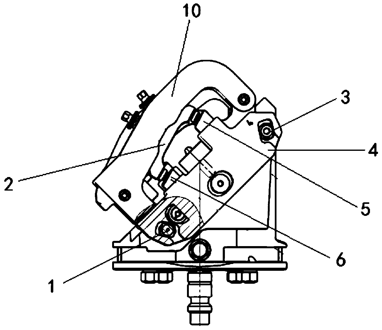
  • An airfoil clamping device for machining precision forged blades of aero-engines
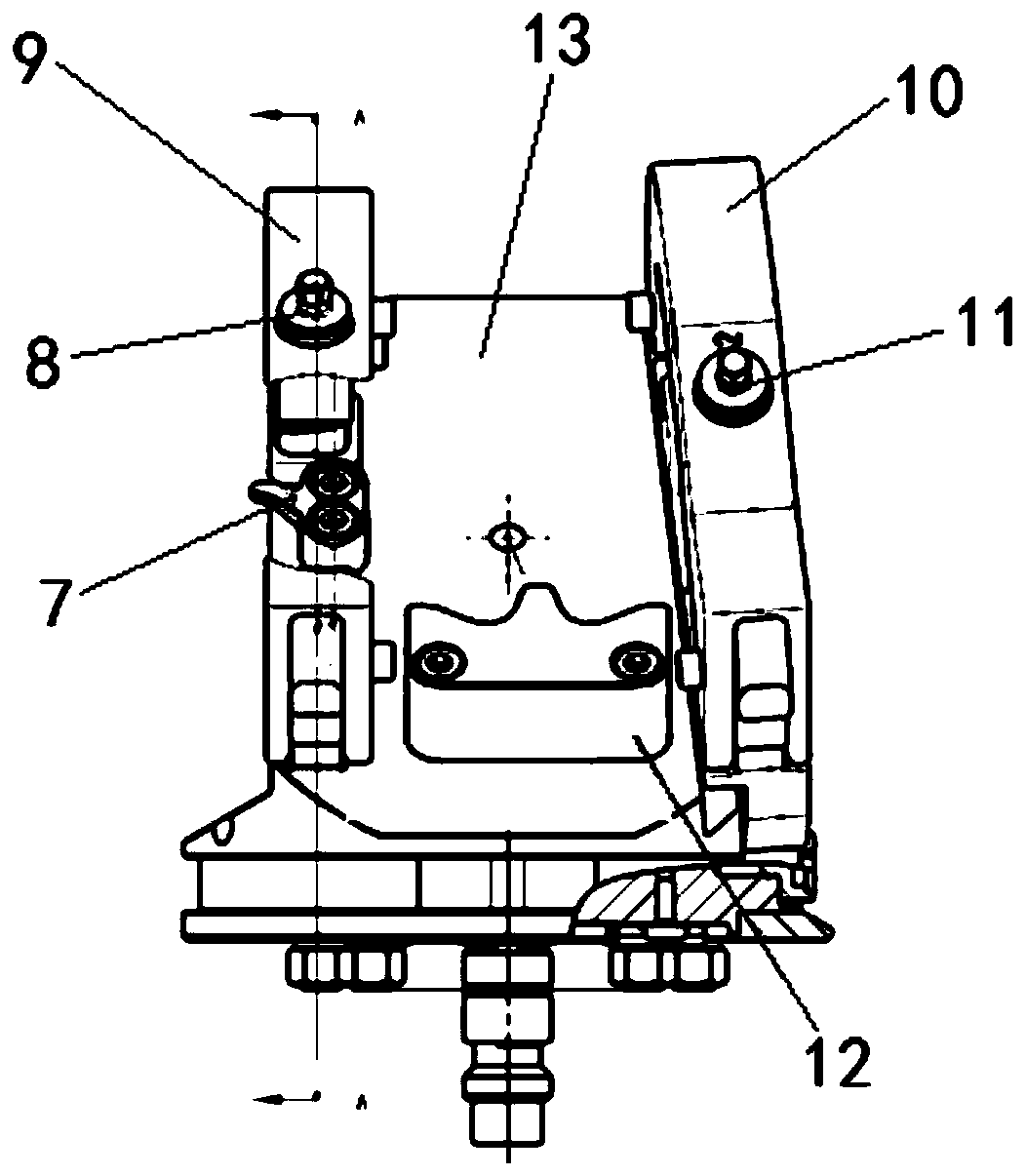
  • An airfoil clamping device for machining precision forged blades of aero-engines
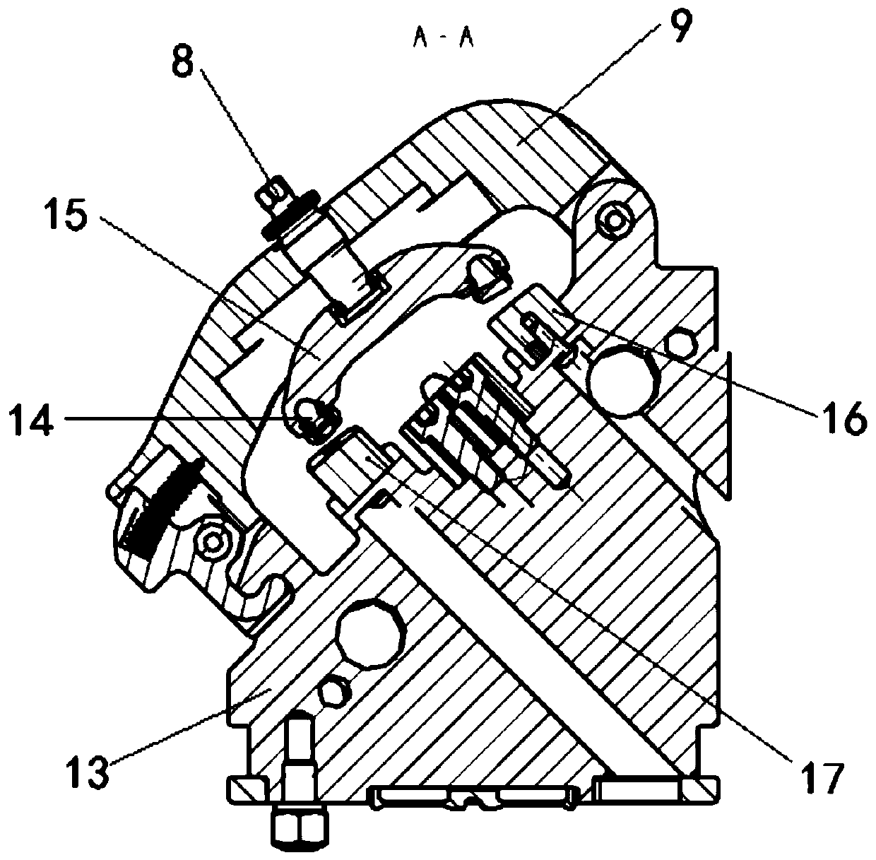
  • An airfoil clamping device for machining precision forged blades of aero-engines

Examples


Embodiment Construction

[0022] Below in conjunction with accompanying drawing, the present invention is described in further detail:

[0023] see Figure 1 to Figure 3 , a blade type clamping device for the machining of aero-engine precision forging blades, comprising a fixed clamping base 13, one side of the fixed clamping base 13 is connected with a movable clamping base 4 through a connecting shaft, and the movable clamping base 4 The fixed clamping base 13 is movably connected with a first fixed pressing mechanism 9, one end of the first fixed pressing mechanism 9 is hinged on the fixed clamping base 13, and the other end is connected to the fixed clamping base 13 through a buckle. The fixed clamping base 13 is connected, and the movable clamping base 4 is movably connected with a second fixed pressing mechanism 10. One end of the second fixed pressing mechanism 10 is hinged to the movable clamping base 4, and the other end is connected to the movable clamping through a buckle. The base 4 is con...


PUM


Abstract

The invention discloses a blade profile clamping device for machining of a precision forging blade of an aero-engine. The blade profile clamping device comprises a fixed clamping base; one side of thefixed clamping base is connected with a moving clamping base, the fixed clamping base is movably connected with a first fixed compaction mechanism, and a second fixed compaction mechanism is movablyconnected with the moving clamping base; a first blade profile fixed supporting block and a second blade profile fixed supporting block are arranged on the fixed clamping base, and a first blade profile type floating compaction mechanism for compressing the blade is connected with the first fixed compaction mechanism; and a first blade profile moving supporting block and a second blade profile moving supporting block are arranged on the moving clamping base, a second blade profile floating compaction mechanism for compressing the blade is connected to the second fixed compaction mechanism, anda flange plate positioning block for positioning the edge plate end of the blade and an air inlet edge positioning block for positioning the air inlet edge of the blade are further arranged on the fixed clamping base. The blade profile clamping device satisfies the requirements of being low in clamping deformation, high in clamping rigidity and being without pressing and damaging the blade.

Description

technical field [0001] The invention belongs to the field of rapid and precise positioning, and in particular relates to a blade type clamping device used for machining precision forging blades of aero-engines. Background technique [0002] At present, tin-bismuth alloy casting and positioning are generally used for the positioning of precision forging blades, which has the problems of complicated process flow and long production cycle. Due to the problems of clamping deformation, insufficient rigidity and crushing of the blade profile in the direct positioning tool for precision forging blade profiles, the direct positioning process has not been widely used. SUMMARY OF THE INVENTION [0003] The purpose of the present invention is to provide an airfoil clamping device for the machining of precision forged blades of aero-engine to solve the problems of the prior art. Require. [0004] To achieve the above object, the present invention adopts the following technical solut...

Claims


Application Information

Patent Timeline
Patent Type & Authority Patents(China)
IPC IPC(8): B23Q3/06
CPCB23Q3/062
Inventor 许立君王茂民赵春蓉李飞杨林张义德张新冬朱坚伟
Owner AECC AVIATION POWER CO LTD
Learn More