
Dental high-speed turbine handpiece

A turbo, high-speed technology, applied in dentistry, dental drilling, medical science, etc., can solve problems such as back-suction pollution, achieve energy saving, ensure sterility safety, and solve the effects of back-suction pollution

Inactive Publication Date: 2018-11-02
圆融医疗设备(深圳)有限公司
View PDF3 Cites 0 Cited by
  • Summary
  • Abstract
  • Description
  • Claims
  • Application Information

AI Technical Summary

Problems solved by technology

[0005] Therefore, in view of the above-mentioned problems, the purpose of the present invention is to provide a dental high-speed turbine handpiece, which has a sterilizing function, and can sterilize the water and gas pipelines therein, thereby solving the problems in the use of the dental high-speed turbine handpiece. Suckback pollution problem

Method used


Image

  • Dental high-speed turbine handpiece
  • Dental high-speed turbine handpiece
  • Dental high-speed turbine handpiece

Examples


Embodiment Construction

[0023] In order to make the object, technical solution and advantages of the present invention clearer, the present invention will be further described in detail below in conjunction with the accompanying drawings and specific embodiments. It should be understood that the specific embodiments described here are only used to explain the present invention, and are not intended to limit the present invention.

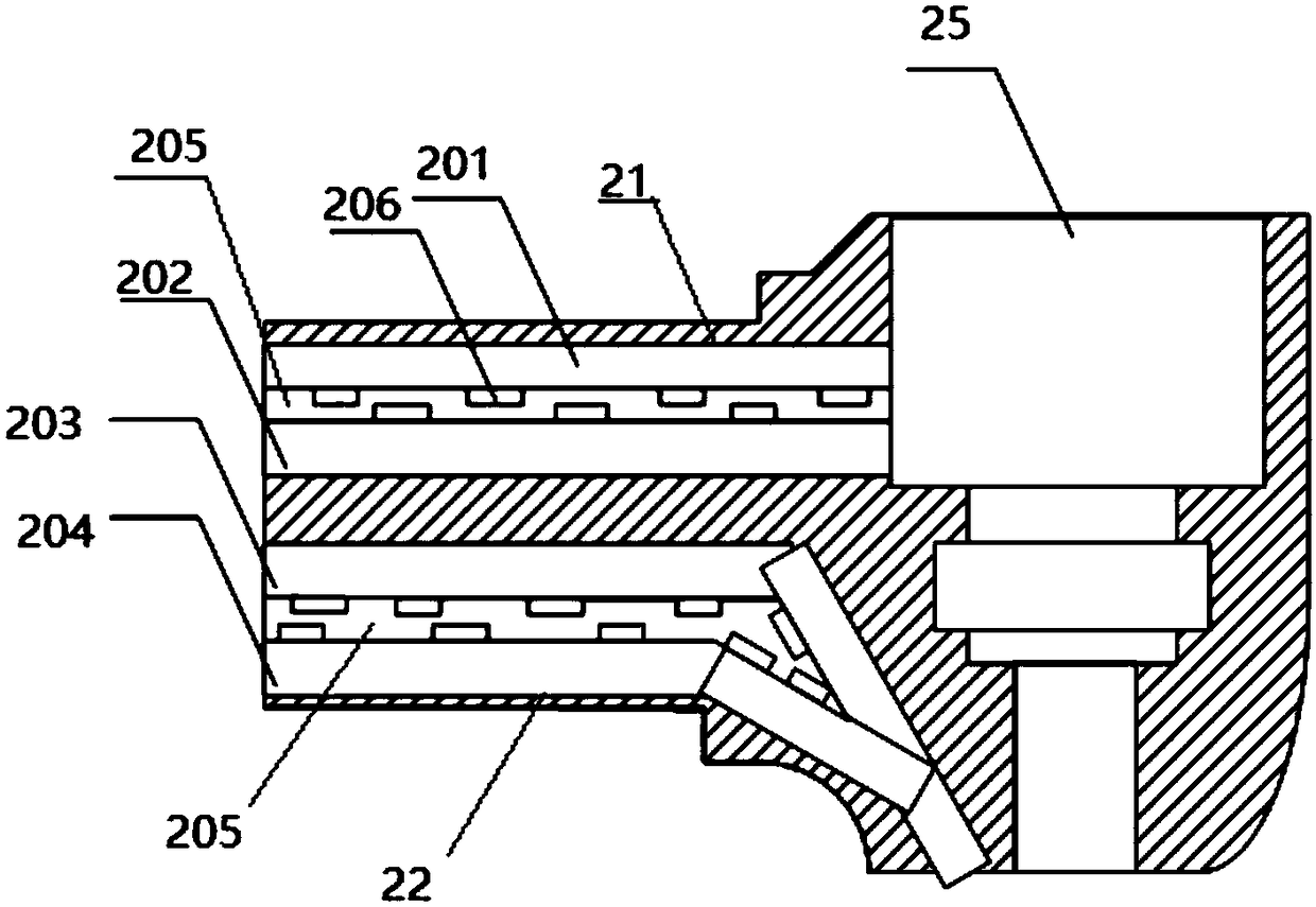
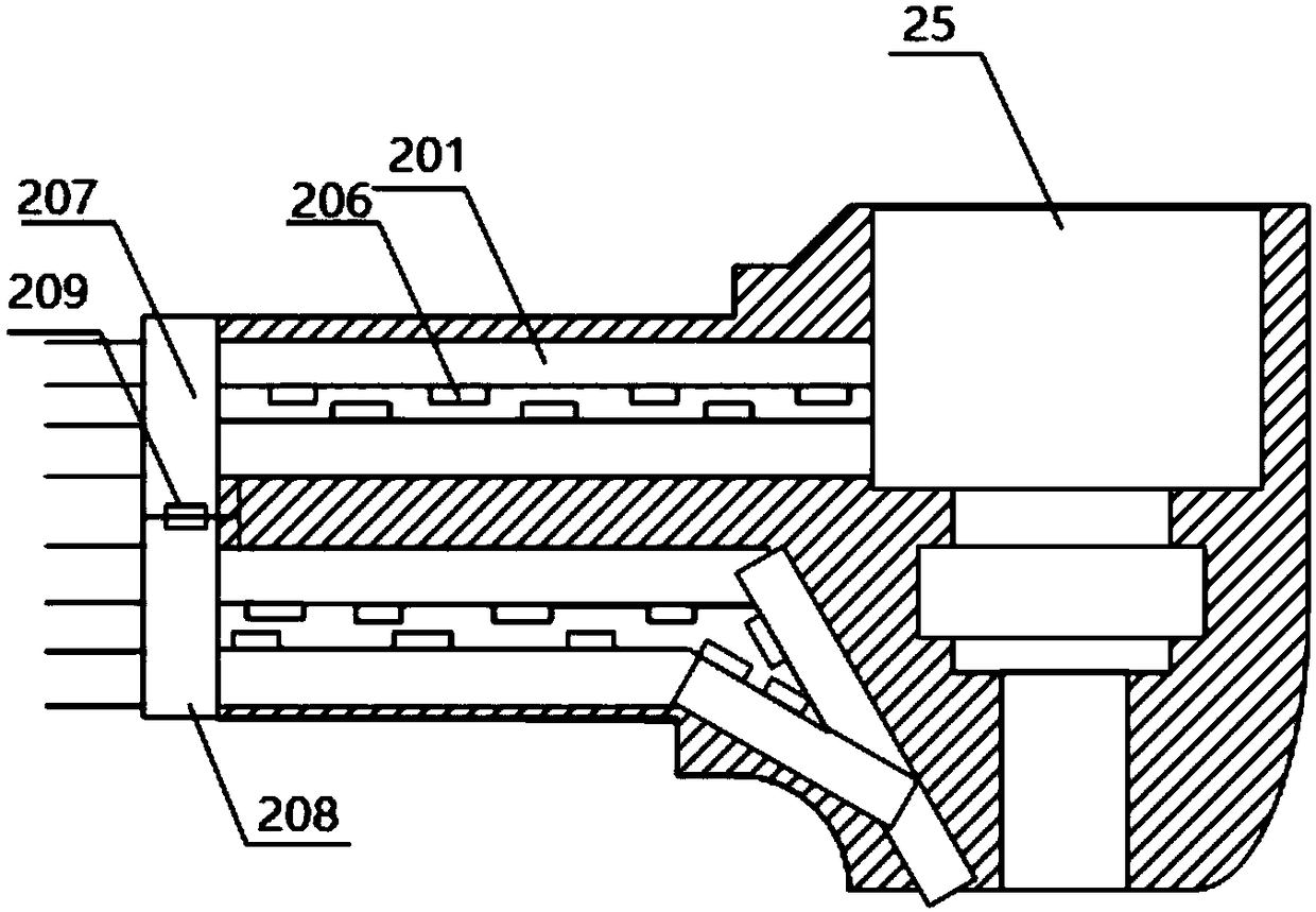
[0024] One embodiment of the present invention provides a dental high-speed turbine handpiece, such as figure 2 As shown, the dental high-speed turbine handpiece includes a head 25 and a water delivery gas pipeline connected to the head, a turbine and a collet are arranged in the head, the turbine is arranged in the collet, and the water delivery The air pipeline includes a driving air pipe 21 for driving the turbine to rotate and a cooling pipe 22 for cooling, and it is characterized in that a sterilizing device is arranged in the driving air pipe and the cooling pipe. ...


PUM


Abstract

The invention discloses a dental high-speed turbine handpiece. The dental high-speed turbine handpiece comprises a handpiece body and a vapor conveying pipeline connected with the handpiece body, wherein a turbine and a barrel clamp are arranged in the handpiece body; the turbine is arranged in the barrel clamp; the vapor conveying pipeline comprises a driving air pipe for driving the turbine to rotate and a cooling pipe for cooling. The dental high-speed turbine handpiece is characterized in that sterilizing devices are arranged in the driving air pipe and the cooling pipe. Through arrangement of the sterilizing devices in the vapor conveying pipeline, the vapor conveying pipeline can be disinfected, thus resolving the problem of back-suction pollution of the dental high-speed turbine handpiece.

Description

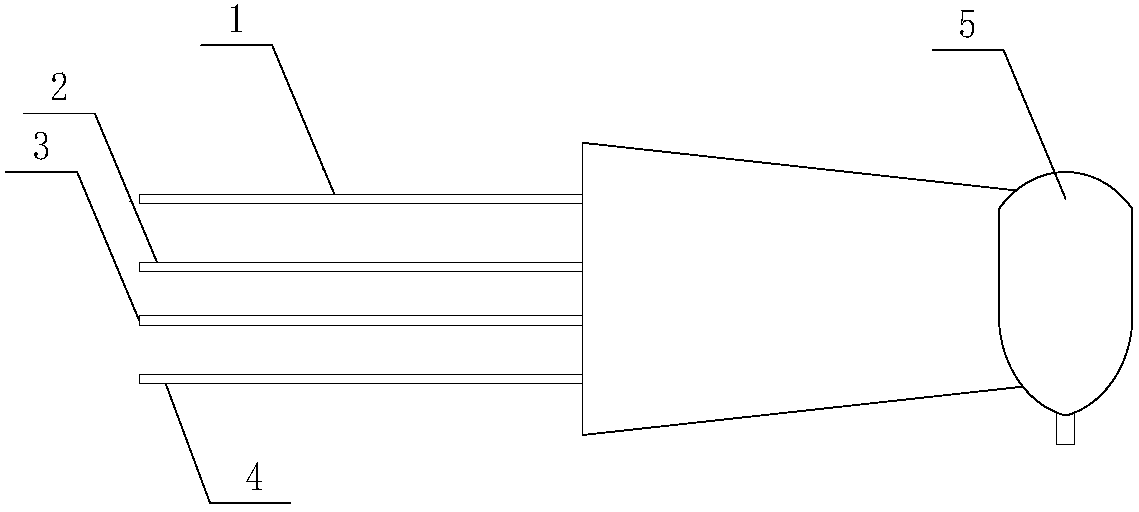
technical field [0001] The invention relates to the technical field of dental equipment. More specifically, the present invention relates to a dental high speed turbine handpiece. Background technique [0002] As an important dental medical equipment, dental handpieces can generally be divided into dental high-speed handpieces and dental low-speed handpieces. Dental high-speed turbine handpieces commonly used in dental high-speed handpieces, figure 1 A schematic diagram of its simple structure is shown, such as figure 1 As shown, the main body of the dental high-speed turbine handpiece is the head 5, and the rear end of the head is connected with a water delivery air pipeline composed of a driving air flow pipe 1, a return air pipe 2, a cooling water pipe 3, and a cooling air pipe 4. When the dental high-speed turbine handpiece is working, the water-air pipeline is connected to the central water-air system, and the high-pressure driving airflow drives the turbine to rotat...

Claims


Application Information

Patent Timeline
Patent Type & Authority Applications(China)
IPC IPC(8): A61C1/05
CPCA61C1/052
Inventor 丛巍梁旭东
Owner 圆融医疗设备(深圳)有限公司
Learn More