
Electric intraosseous infusion system

An electric, infusion needle technology, applied in the field of medical devices, can solve the problems of inconvenience to carry out, long operation time, broken infusion needle, etc., and achieve the effect of improving speed and convenience, ensuring sterile safety, and improving safety.

Active Publication Date: 2021-01-01
南昌大学第一附属医院
View PDF6 Cites 0 Cited by
  • Summary
  • Abstract
  • Description
  • Claims
  • Application Information

AI Technical Summary

Problems solved by technology

The manual FAST1 system and the ejection BIG system rely on mechanical force and spring mechanical force to perform puncture, which have high technical requirements for the operator, long operation time, and are likely to cause fractures at the puncture site, severe pain, and breakage of the infusion needle. At the same time, due to uneven strength or operator error, the infusion needle is not fixed firmly, which may cause the infusion needle to fall off and leak, which will lead to serious complications such as osteofascial compartment syndrome.
[0004] The electric EZ-IO system uses electricity to rotate the infusion needle into the bone marrow, avoiding the defects of the previous two intraosseous infusion systems, but this system needs to manually install the infusion needle on the drill bit and remove the infusion needle protective cover The puncture can only be performed after it is inserted, so the requirements for disinfection operations are high, and the system needs to prepare puncture needles of different lengths according to different puncture sites, which is not easy to carry out

Method used


Image

  • Electric intraosseous infusion system
  • Electric intraosseous infusion system
  • Electric intraosseous infusion system

Examples


Embodiment Construction

[0028] The present invention will be described in detail below in conjunction with the embodiments and the accompanying drawings. However, the following examples should not be considered as limiting the scope of the present invention.

[0029] In the description of the present invention, it should be noted that the orientation or positional relationship indicated by the terms "upper", "lower", "left", "right", etc. is based on the orientation or positional relationship shown in the drawings, and is only for It is convenient to describe the present invention and simplify the description, but does not indicate or imply that the device or element referred to must have a specific orientation, be constructed and operate in a specific orientation, and thus should not be construed as limiting the present invention.

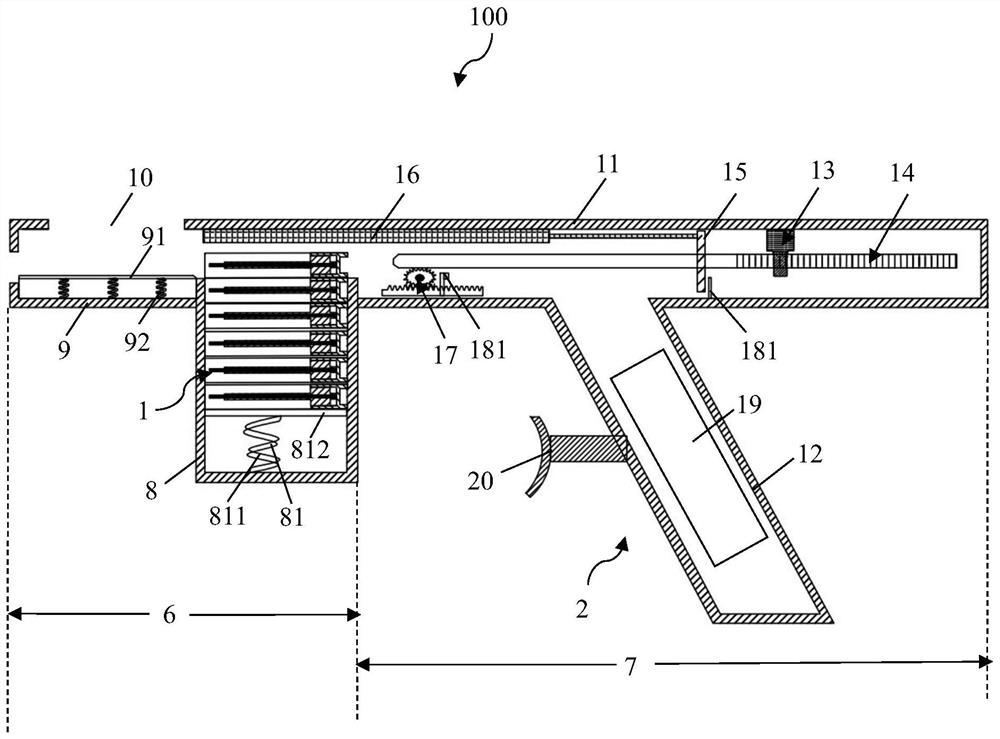
[0030] figure 1 It is a schematic diagram of the overall structure of the electric intraosseous infusion system in the embodiment of the present invention.

[0031] Su...


PUM


Abstract

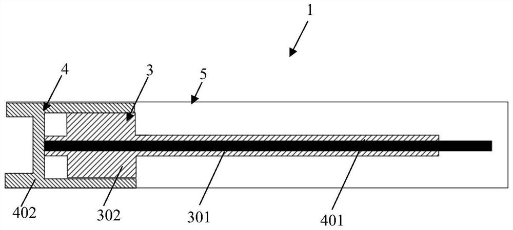
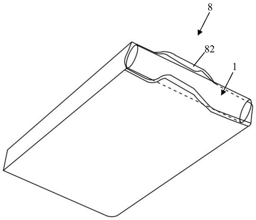
The invention provides an electric endosseous infusion system. The electric endosseous infusion system comprises an infusion needle component and a puncturing control component, wherein the infusion needle component comprises an infusion needle assembly, a puncturing needle assembly and a shell assembly; the puncturing control component is in the shape of a gun, and comprises two parts namely an emitting bin and a power bin; the emitting bin comprises an automatic needle pushing assembly, a magazine type needle storing box, a shell ejection assembly arranged at the front end of the magazine type needle storing box and a shell ejection window formed in the upper part of the shell ejection assembly; the power bin comprises a needle pushing bin and a power source bin; a power assembly, a transmission assembly of which one end is connected with the power assembly and the other end cooperates with a sleeve, a depth limiting blocking piece mounted on the transmission assembly, a sliding cover plate of which one end is fixedly connected with the depth limiting blocking piece and the other end can cover the shell ejection window under the pushing of the depth limiting blocking piece, an adjustable depth limiting indicating assembly and a depth limiting blocking piece limiting mechanism are arranged in the needle pushing bin; and a power source is arranged in the power source bin, and acontact button is arranged on the outer wall of the power source bin.

Description

technical field [0001] The invention belongs to the technical field of medical devices, and in particular relates to an electric intraosseous transfusion system for quickly establishing a fluid resuscitation channel during emergency rescue. Background technique [0002] It is very important to quickly establish the infusion channel in the rescue to ensure the infusion and drug administration. Bone marrow infusion technology is currently the only non-venous infusion method. Compared with traditional intravenous infusion technology, it has the advantages of convenience, speed, safety, high success rate, and the operator does not need long-term professional training. This technology expands the effective needle application area from a few millimeters of the vein to 4-5 cm in the flat area of ​​the bone. It is easier to locate patients with collapsed veins and has a higher success rate of needle application. It can be quickly implemented even at the rescue site and during transp...

Claims


Application Information

Patent Timeline
Patent Type & Authority Patents(China)
IPC IPC(8): A61B17/34A61M5/14
CPCA61B17/3472A61B17/3494A61M5/14
Inventor 潘淑婷黄淦
Owner 南昌大学第一附属医院
Learn More